The XY stage also includes hall effect limit switches and 2000 step shaft encoders. A great find, the challenge now is to build a machine that does it justice.Bipolar versus Unipolar drive
Stepper motors usually contain two electromagnets which need to be energised in one of two magnetic polarities, giving four combinations or phases. If this is done with a single coil per electromagnet then the electronics must be able to drive a positive or negative current into each coil. This is bipolar drive and requires four transistors per coil, i.e. eight per motor. Alternatively the coils can be centre tapped which effectively creates two coils per electromagnet wound in opposite directions. One of these can be energised at a time to produce opposite magnetic fields. This only requires one transistor per half coil, i.e. four per motor. The advantage of unipolar is that the electronics are cheaper but as only half of the windings are energised at one time the amount of torque available from a given size of motor is less.The field produced by an electromagnet and hence the torque of the motor is proportional to the number of turns times the current. The maximum current that can be applied is limited by the maximum allowable temperature rise. The heat generated in the windings is proportional to current squared times resistance. This means that if a unipolar motor is operated in bipolar mode then the maximum current is root two times less because the resistance of the full winding is double that of the half windings. However, the number of turns is doubled so the torque is root two greater.Constant current versus constant voltage
The simplest way to drive a stepper is to apply a constant voltage to the coils. The problem with this is that when a voltage is applied to a coil the current builds up gradually at a rate proportional to the voltage divided by the inductance until it reaches the steady state defined by the voltage divided by the resistance. This causes torque to fall off with speed because at higher step rates the current does not get time to reach its full value before the next step.
A better driver system is to apply a much higher voltage to the coil to get the current to rise quickly and then turn it off when it reaches the correct value. The current then starts to fall at which point the voltage is applied again. This on / off switching occurs at a high enough frequency to avoid producing audible noise.Micro-stepping
This is a technique to increase the number of steps per revolution by varying the current in the two windings in a sinusoidal fashion. In this case it increases the number of steps from 200 to 2000 per rev. As the screw threads have half an inch travel per rev this gives me a step size of a 4000th of an inch or just over 6 micrometers. The target for RepRap V1.0 aka Darwin is 0.1mm resolution so I am well within that that! The only downside is that the maximum travel is only 150mm in each direction compared to Darwin's 300mm.
Another advantage of micro-stepping is that it produces smoother running at low speeds.Anti-resonance
Because the force applied by the motor increases as it is displaced from its resting position it behaves like a spring. This together with the mass of the rotor and the load forms a resonant system. If the step rate gets close to the resonant frequency oscillations build up and the motor gets out of step and / or stalls. This is a major problem with high speed operation of stepper motors. An anti-resonant drive monitors the drive waveforms to detect when resonance starts to occur and adjusts the drive current to dampen it down. This allows the motor to be stepped through its resonant band to achieve higher speeds. Clever stuff!Opto isolated inputs
The step and direction inputs are electrically isolated from the drive electronics by opto couplers. This avoids heavy motor currents sharing the same ground path as the logic signals, which can cause signal corruption.
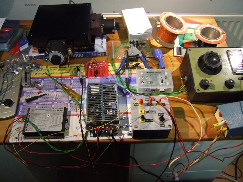
Here it is being put through its paces with a signal generator on one axis.


No comments:
Post a Comment