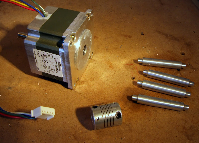
I used a flexible coupler, shown above, to join the motor shaft to the drive screw. This allows for slight misalignment. A cheap alternative can be made from plastic or rubber tubing and pipe clips but I had a couple in my junk collection so I used one. This may have been a mistake because the z-axis is very noisy when it is running. This is made worse by the fact that it is mounted on an MDF box structure which resonates. A softer coupling may help here. Another idea I had was to fill the box with something to dampen the sound, fine sand perhaps, I am open to suggestions.
BTW, if anybody is interested, there were more of these axes available here when I last looked.
The z-axis only needs to move relatively slowly so I used a simple unipolar drive circuit based on a ULN2803 octal darlington driver chip. I paired up the channels to get enough current because with only 3.3V inputs they are derated somewhat. The 2803 has internal clamping diodes to protect it from the back e.m.f. generated when a winding is turned off. Rather than tie these to a zener off the positive rail, like the RepRap version does, I clamped the outputs to ground with some external diodes. This makes use of the fact that each centre-tapped winding behaves like an auto transformer, so if you stop one end going below zero you stop the other end going above twice the supply rail, in my case 48V. This technique has the advantage of returning the energy in the coil to the supply rail, rather than dissipating it in the zener. It has the slight disadvantage that if you disconnect the motor while the power is on you risk damaging the driver. I used fast recovery rectifiers salvaged from the same broken PC power supply I mentioned before. These will perform better than ordinary rectifiers if I do any high frequency PWM for micro stepping.
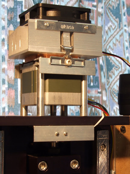
The motor got quite hot when it has been on a while, leveling off at about 60°C. It is, after all, dissipating about 19W. While I didn't think this was a big problem I decided to stick a spare CPU heatsink and fan on the top. I ran this from 5V rather than 12V to keep the noise down. It reduces the temperature to about 40°C. With a constant voltage drive, keeping the temperature down stops the torque falling off due to increased winding resistance.
The next step is to write some code and test the axes.


Well, you look to have your cartesian positioning system in hand. Now you need to get acquainted with the vagarities of the Mk II extruder. :-)
ReplyDeleteGreat work!
Yes, a small matter of software first though.
ReplyDeleteAlthough you've been running this for a couple of years now, fwiw your stepper looks like a NEMA23. The easy way to tell would be to measure it - if it is 2.3" across, it's a 23! Yes, it is that simple! a 17 is 1.7", and so on.
ReplyDeleteBut yes, you've got a version where the drive shaft is sticking out the wrong end. You can get them with a shaft from both ends too. Just depends on the part number, really.