I put new PET tape on my heated bed at the beginning of July. Since then I have printed 15 Mendels on it, but on the last few I was getting problems with the parts not sticking. That is after about 700 hours of printing and ~15kg of plastic. I occasionally swab it down with Isopropanol to remove grease from finger prints, but Isopropanol is not a solvent for ABS. This evening I tried cleaning it with acetone instead. It dramatically increased the grip level, restoring it to new and making the parts hard to remove again! ABS must leave some traces behind on the surface of the bed and the acetone removes it.
So it looks like PET tape is almost fully reusable. It tends to get the odd blister where the corners of big objects overcome its adhesive and picks up a few scars from the odd accident with a knife. Apart from that it just needs cleaning with acetone about once a month.
Monday 9 August 2010
Monday 19 July 2010
A bit of a drag
One problem I have had, on and off, with Mendel is a tendency for the infill not to meet the outline. This was particularly bad with PLA. I have combated this by having some infill overlap and also extruding the plastic slightly faster than it should be, so that the solid layers are well stuffed. I don't have to do either of these things with HydraRaptor. I couldn't figure out what the difference was until I changed a reel of plastic recently. The first print on the new reel came out like this: -

The gap is always at one side like this, it is as if the infill is not centred within the outline. The reason, I have come to realise, is that the belt has some play in it because it is not infinitely taught. When the extruder pulls filament off a reel it exerts a force on the carriage, which displaces it slightly from where it would come to rest without any external force. Because the carriage moves, the filament only gets pulled from the reel at the local extremes of movement, the rest of the time it is slack. This causes small offsets in the filament paths. In particular, when it is doing zigzag infill it is using filament relatively quickly, so at the end of the zigzag furthest from the centre of the bed it is likely to give a little tug of the reel each time, causing the zigzag to stop short of the outline.
The conclusion is that the filament feed for a belt-driven moving-head machine needs to be very low drag. The hanging basket technique that I used on HydraRaptor is no good because it has to pull plastic out from under its own weight. Making the feed point high above the machine reduces the lateral drag on the carriage, but you can easily get enough vertical drag to deflect the x-bars upwards, or even lift the z-axis slightly because the backlash in the thread is only taken up by the weight of the x-axis.
The reason it was bad with PLA was because I was pulling it from a hanging basket and being very stiff, even a small coil needs a lot of tug.
The system I now use is a vertically mounted spool big enough to take 5kg coils, which last me a couple of weeks.

The bearing is just a stainless steel axle running in PLA bushes, lubricated with some lithium grease. It is low friction, but not as frictionless as a ball bearing. It needs a little friction to stop any in-balance in the coil causing the spool to spin to its low point. Also the faces of the spool need to be quite big to stop a loose loop of filament coming over the side. It pulls tight and jams if that happens.
I can take the spool apart to insert a new coil of plastic.

In general though I have to wind it all off and on again to get it tight and balanced enough to wind off smoothly. Since 5kg is about 800m it takes a long time to wind it onto a garden hose reel and then back on again. Someday I will get round to making a machine to do it for me. In the meantime I will make a second identical spool so that I can just mount the coil on one spool and wind it onto a second one to use.

The gap is always at one side like this, it is as if the infill is not centred within the outline. The reason, I have come to realise, is that the belt has some play in it because it is not infinitely taught. When the extruder pulls filament off a reel it exerts a force on the carriage, which displaces it slightly from where it would come to rest without any external force. Because the carriage moves, the filament only gets pulled from the reel at the local extremes of movement, the rest of the time it is slack. This causes small offsets in the filament paths. In particular, when it is doing zigzag infill it is using filament relatively quickly, so at the end of the zigzag furthest from the centre of the bed it is likely to give a little tug of the reel each time, causing the zigzag to stop short of the outline.
The conclusion is that the filament feed for a belt-driven moving-head machine needs to be very low drag. The hanging basket technique that I used on HydraRaptor is no good because it has to pull plastic out from under its own weight. Making the feed point high above the machine reduces the lateral drag on the carriage, but you can easily get enough vertical drag to deflect the x-bars upwards, or even lift the z-axis slightly because the backlash in the thread is only taken up by the weight of the x-axis.
The reason it was bad with PLA was because I was pulling it from a hanging basket and being very stiff, even a small coil needs a lot of tug.
The system I now use is a vertically mounted spool big enough to take 5kg coils, which last me a couple of weeks.

The bearing is just a stainless steel axle running in PLA bushes, lubricated with some lithium grease. It is low friction, but not as frictionless as a ball bearing. It needs a little friction to stop any in-balance in the coil causing the spool to spin to its low point. Also the faces of the spool need to be quite big to stop a loose loop of filament coming over the side. It pulls tight and jams if that happens.
I can take the spool apart to insert a new coil of plastic.
In general though I have to wind it all off and on again to get it tight and balanced enough to wind off smoothly. Since 5kg is about 800m it takes a long time to wind it onto a garden hose reel and then back on again. Someday I will get round to making a machine to do it for me. In the meantime I will make a second identical spool so that I can just mount the coil on one spool and wind it onto a second one to use.
Thursday 8 July 2010
Meltdown
While making its 18th child, my Mendel made a real pig's ear of laying down the first layer holes at the start of a build. So bad that the infill did not join to them and started curling upwards. I had to watch it a while before I realised what the problem was. The extruder had come loose and was bouncing up and down when the filament feed stopped and started.
I thought it was just that the bolts had worked loose but after I tightened them it was still moving and there were some worrying crunching sounds, so it was time to strip it down.

The bottom of the heatsink is covered with a sticky deposit. It is some volatile component that boils off the ABS and condenses on cold surfaces,

The main extruder bracket had broken and the carriage didn't look too good either: -

I stripped the carriage down as well and found that it was cracked and severely distorted.

The main problem I realised is my modified hot end. Normally the insulator is locked into the chunky part of the bracket by a couple of M3 bolts through it. I can't get those in because my heatsink is in the way, so I rely on the mounting bolts and the upper carriage to take the extrusion force. On reflection, not a good idea!

The lower carriage is less deformed because the extrusion force does not pass though it.

The heat rising from the bed and the extruder must be enough to soften the carriage and let it deform, but also it seems to have made the ABS weak and crumbly. Even the belt clamps have deformed.

This is after about 3 months of printing though so it isn't a big problem to replace them as long as you have spares. I had just printed a carriage before it failed so it was easy to replace but I had to print another extruder on HydraRaptor. You really need to have a full set of spares on hand, or have two machines.
I did various changes to make it more durable. The main thing is I fitted nuts under the heatsink so that no force goes through the carriage. I also put large penny washers on the top of the extruder bracket to reinforce the lugs. Ideally they should be a bit thicker but that would reduce the Z travel even further. The extruder motor clashes with the frame which reduces the height. Then my heatsink loses another 10mm or so and my heated bed loses 26mm. I am left with about 35mm which is only just enough to build the tallest Mendel part (the lower carriage).
I also used nyloc nuts in the captive positions in the carriage. The wiki advises against this as it may crack the plastic but it doesn't seem to be case with my ABS parts. Ordinary nuts don't stay tight because the plastic creeps.


I intend to fit some sort of heat shield to stop the heat rising from the bed reaching the carriage. In the mean time I have started fitting the front on my cabinet after the first layer is finished, when the bed temperature drops from 140°C to 110 °C. That can be up to 90 minutes into the build, so not convenient.
Saturday 3 July 2010
ABS on PC
My last heated bed ran for a long time but it finally went pop on Mendel print number 15. The TO220 resistors developed a short to earth about half way though an 8 hour overnight build. It took out a 5 Amp mains fuse and destroyed the 4 Amp solid state relay that was controlling it.
Clearly the cheap TO220 resistors are just not suitable for abusing as heating elements, so I went back to using aluminium clad resistors. The disadvantage is that they are higher profile and need two accurately drilled mounting holes, but they are a lot more robust and cheaper. The more expensive TO220 resistors I used on HydraRaptor are still going strong, but there is nothing to suggest that they are any better in their spec. It is the tab insulation that breaks down though, so it could be just the fact that the voltage is much lower on HydraRaptor.
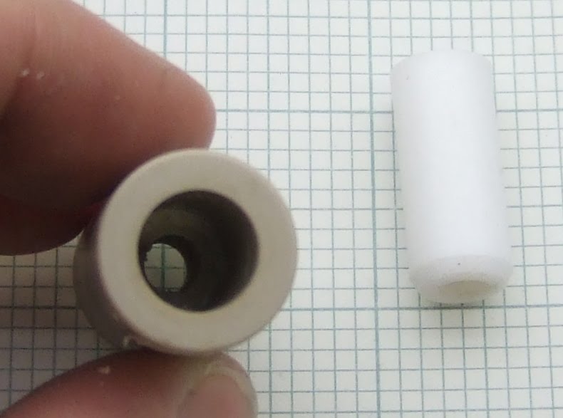
I have used the Tyco THS10 series at temperatures up to 240°C and not had any fail yet. They are not rated for mains voltage though, so I moved up to THS15 series which are. They are slightly taller, which doesn't actually matter because I use 20mm stand-offs, so there is still sufficient gap. The mounting holes will take an M2.5 screw, but I didn't have any to hand, so I drilled them out for M3. There is just enough room for a screw head with an integral washer, a standard washer would not fit.
I have run the THS10 at about twice their rating so I did the same with these: 9 × 22Ω in series gives a total power of 290W at 240V. That gives a warm-up time of about 4 minutes to 140°C. My extruder takes longer to get to 255°C, so I set them both off together so that the bed has enough time at its steady state temperature for the nylon pillars to expand fully.

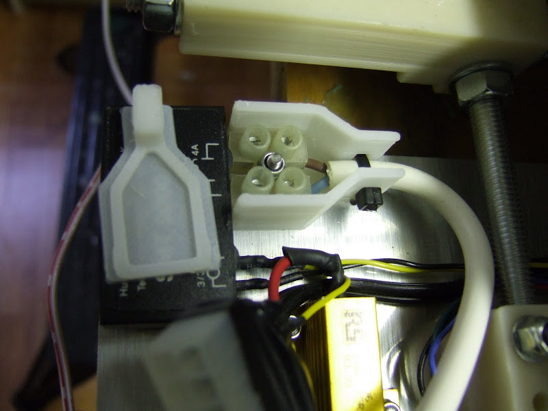
The white PTFE clamp is where I attach the thermocouple. The device wrapped in Kapton tape is a 190°C thermal cut-out to prevent melt down if the firmware crashes or the solid state relay goes short circuit. The mains wire has PTFE insulation to handle the temperature. Since the wiring is exposed it should really have an extra layer of insulation to be considered safe, but I am not about to stick my fingers under a hot bed so I didn't bother. If you have children or animals, or are completely risk averse, then you probably should.
I haven't put any magnets on this one yet as I haven't been making use of the ones on the last bed since I started using white ABS on PET tape. The objects mainly come loose when they cool down and are easily removed without having to remove the steel plate and bend it.
ABS on PET tape works well. The grip level seems to degrade much more slowly than Kapton does. After lots of use it becomes easier to remove objects, but then the amount of grip is not quite enough for some parts. I can make most of the Mendel parts time after time, but I have problems with a few. The outer corners lift slightly towards the end of the build of the large Z brackets when the PET is old and I am building more than one at a time.

Not easy to see, but the bottom right corner has lifted by about 0.5mm. It makes no difference to the function of the part but I like to get them completely flat.

At the opposite end of the scale I have problems with the bed springs and the X 360 Z bearing plates. These are very tall compared to their footprint, so as the nozzle bushes past the top of the objects they often ping off the bed due to the small contact area and the high leverage. When the PET is old I have about a 30% reject rate with these unless I do them one at a time.
I had a 5mm sheet of polycarbonate that I have been meaning to try as a bed material for some time. I think that is what is used on commercial machines. It has a high melting point (267°C), so will not melt when the hot filament lands on it. It also has a high glass transitions (150°C) so shouldn't soften on a heated bed.
I clamped it to the aluminium bed with some bulldog clips.

I tried it cold to start with but the ABS did not stick so I tried it at 140°C next. I made a test shape that I am using to research hole shrinkage. It stuck so well I broke it trying to get it off.

I had to use a chisel to get the rest off. Strangely, although the ABS is extruded below the melt point of the PC, so it can't form a diffusion weld, it forms a stronger bond with the PC than to itself.
I dropped the initial bed temperature to 50°C which seemed to be the lowest I could get the first layer outline to stick properly. After the first layer I set the bed temperature to 90°C to reduce the warping stress in the ABS. These are temperatures on the underside of the aluminium, so the top surface of the PC will be something like 15-20°C lower.

I made these tall objects that tend to come unstuck from PET. These held well, in fact, when I removed them, most of the springs and one of the bearing plates left their bottom layer behind. Not really a big problem, the bottom layer becomes a minimalist raft!
For general production I went back to PET tape. I covered a sheet of 1.5mm thick stainless steel and clamped it down with more bulldog clips. I can swap it with a sheet of glass if I need to do PLA. The steel seems to be strong enough to stay flat in the middle when clamped at the edge.

Clearly the cheap TO220 resistors are just not suitable for abusing as heating elements, so I went back to using aluminium clad resistors. The disadvantage is that they are higher profile and need two accurately drilled mounting holes, but they are a lot more robust and cheaper. The more expensive TO220 resistors I used on HydraRaptor are still going strong, but there is nothing to suggest that they are any better in their spec. It is the tab insulation that breaks down though, so it could be just the fact that the voltage is much lower on HydraRaptor.
I have used the Tyco THS10 series at temperatures up to 240°C and not had any fail yet. They are not rated for mains voltage though, so I moved up to THS15 series which are. They are slightly taller, which doesn't actually matter because I use 20mm stand-offs, so there is still sufficient gap. The mounting holes will take an M2.5 screw, but I didn't have any to hand, so I drilled them out for M3. There is just enough room for a screw head with an integral washer, a standard washer would not fit.
I have run the THS10 at about twice their rating so I did the same with these: 9 × 22Ω in series gives a total power of 290W at 240V. That gives a warm-up time of about 4 minutes to 140°C. My extruder takes longer to get to 255°C, so I set them both off together so that the bed has enough time at its steady state temperature for the nylon pillars to expand fully.

The white PTFE clamp is where I attach the thermocouple. The device wrapped in Kapton tape is a 190°C thermal cut-out to prevent melt down if the firmware crashes or the solid state relay goes short circuit. The mains wire has PTFE insulation to handle the temperature. Since the wiring is exposed it should really have an extra layer of insulation to be considered safe, but I am not about to stick my fingers under a hot bed so I didn't bother. If you have children or animals, or are completely risk averse, then you probably should.
I haven't put any magnets on this one yet as I haven't been making use of the ones on the last bed since I started using white ABS on PET tape. The objects mainly come loose when they cool down and are easily removed without having to remove the steel plate and bend it.
ABS on PET tape works well. The grip level seems to degrade much more slowly than Kapton does. After lots of use it becomes easier to remove objects, but then the amount of grip is not quite enough for some parts. I can make most of the Mendel parts time after time, but I have problems with a few. The outer corners lift slightly towards the end of the build of the large Z brackets when the PET is old and I am building more than one at a time.

Not easy to see, but the bottom right corner has lifted by about 0.5mm. It makes no difference to the function of the part but I like to get them completely flat.

At the opposite end of the scale I have problems with the bed springs and the X 360 Z bearing plates. These are very tall compared to their footprint, so as the nozzle bushes past the top of the objects they often ping off the bed due to the small contact area and the high leverage. When the PET is old I have about a 30% reject rate with these unless I do them one at a time.
I had a 5mm sheet of polycarbonate that I have been meaning to try as a bed material for some time. I think that is what is used on commercial machines. It has a high melting point (267°C), so will not melt when the hot filament lands on it. It also has a high glass transitions (150°C) so shouldn't soften on a heated bed.
I clamped it to the aluminium bed with some bulldog clips.

I tried it cold to start with but the ABS did not stick so I tried it at 140°C next. I made a test shape that I am using to research hole shrinkage. It stuck so well I broke it trying to get it off.

I had to use a chisel to get the rest off. Strangely, although the ABS is extruded below the melt point of the PC, so it can't form a diffusion weld, it forms a stronger bond with the PC than to itself.
I dropped the initial bed temperature to 50°C which seemed to be the lowest I could get the first layer outline to stick properly. After the first layer I set the bed temperature to 90°C to reduce the warping stress in the ABS. These are temperatures on the underside of the aluminium, so the top surface of the PC will be something like 15-20°C lower.

I made these tall objects that tend to come unstuck from PET. These held well, in fact, when I removed them, most of the springs and one of the bearing plates left their bottom layer behind. Not really a big problem, the bottom layer becomes a minimalist raft!
For general production I went back to PET tape. I covered a sheet of 1.5mm thick stainless steel and clamped it down with more bulldog clips. I can swap it with a sheet of glass if I need to do PLA. The steel seems to be strong enough to stay flat in the middle when clamped at the edge.

Thursday 1 July 2010
Broken bracket breakdown
Whilst printing a 16th set of Mendel parts, my Mendel printed a bed of brackets with bits missing: -

On investigation I found the idler bracket on the extruder had broken, so there wasn't any pressure on the pinch wheel.

It lasted a long time before it broke but clearly it wasn't strong enough. Wade made his in PLA, which is harder and I only use two of the four bolt holes, so mine is under more strain.
I made a stronger replacement. It is thicker and a little bit bigger in the other two dimensions. I also made the holes 4.5mm rather than 4mm so it slides on the bolts easier and I capped the ends of the axle holder as mine tended to slide sideways.

The files are on Thingiverse.
Saturday 12 June 2010
Wooden overcoat
I can make raft-less ABS objects on a heated bed pretty reliably, but when I try to do a whole bed full I get corners lifting on the objects near the edge of the bed. I think the reason is that the air around them is not as hot. If you think about it, with a moving bed machine like HydraRaptor, if you have a single object in the centre of the bed then you have a buffer of hot air around it. The bed only has to move by the dimensions of the object, so if the object is less than half the size of the bed then it remains inside that buffer. When you make objects near the edge of the bed the buffer is smaller and the bed moves further, so you get a double effect. To mitigate this effect I have halved the size of my biggest build trays. This is less convenient as a full bed is about 8 hours giving three shifts a day.
For example, with natural ABS on Kapton I was able to get away with a full bed like this: -

... but with white ABS on PET tape I would always get the odd part around the edge lifting, so I have to do it as two builds now. I bought a new reel of natural ABS from MakerBot but I can't make it work with HydraRaptor. I made a couple of objects but then it started to always jam after a few layers. The reason seams to be that because it is undersized at about 2.8mm, and my barrel has an internal diameter of 3.6mm, molten plastic back-flows up the barrel as far as the cold zone, where it freezes and makes the filament hard to push. This causes the filament to buckle and jam. I don't understand what has changed. The last reel I got from MakerBot a long time ago was the same diameter and I only finished using it recently and had no problems in the same extruder with the same settings. I switched back to white ABS and it works reliably again, so it must be something to do with the plastic.
Another problem with ABS is the fumes. My Mendel extruder seems to give off more fumes than HydraRaptor's does, perhaps because the melt zone is much bigger, and the white ABS seems to smell more acrid than natural ABS. I did a build with a window open to get rid of the fumes but most of the parts then warped, presumably because there was no longer a buffer of warm air around them, but a cool breeze.
In an attempt to tackle both of these problems I built an MDF box around my Mendel.

The front of the box is held on by magnetic door catches. It is sealed by door draft extruder strips and has a window made from plastic from a picture frame. This is glued on with silicone sealant.
The box is tall enough to allow the filament to enter through a single hole in the middle of the roof with a felt gasket that catches the dust.

The fumes are extracted by a tiny fan mounted in a chimney in the roof and piped out through a window vent.


I made a little pipe with a flange that fits into a slot in the vent and taped up the other slots with PET tape. I have another vent in the other window for fresh air in.
This fan is controlled by a spare output on my extruder controller and I have a thermistor to sense the air temperature in the middle of the chamber at the height of the top of the Mendel frame. Together with a small fan to cool the extruder heatsink and a large fan to cool the bed that uses up all the free outputs of my extruder controller, but not for the uses I originally envisaged.

I set the target chamber temperature to 40°C because that is as high as I dare to run the electronics and power supply. With the front closed the small fan cannot hold the temperature down and I have seen it go as high as 50°C without any ill effects. The extruder stepper was then too hot to touch though. Note there is no chamber heater. All the heat comes from the uninsulated bed, extruder and the motors and electronics, so I have actually reduced the total power consumption slightly and gained a heated chamber. To maintain 40°C I have to leave the front open at the bottom. I will add some vents at the bottom of the sides to allow cool air in and perhaps use a bigger fan.
Even with a gap at the bottom of the door I cannot smell any fumes. Since using the chamber nothing has warped provided the first layer outline went down properly as discussed in my last post. It also makes the machine very quiet although it was already much quieter than HydraRaptor.
Monday 24 May 2010
Black and White
I bought some new ABS filament from reprapsource.com as it is a reasonable price, the postage from Germany is not too bad and being in the EU there are no customs charges, so it does not get held to ransom by Parcel Force for their ridiculous handling charge.
I also find PLA has a tendency to do this on my Mendel but not on HydraRaptor. For a sanity check I built the same object from the same g-code with black ABS.
The advert does not state a colour so I assumed it would be natural, however when it came it wasn't like any ABS I had encountered before. Natural ABS is cream coloured and opaque. This was white and a bit translucent. At first I though it was HDPE, but when bent it bruised, which is a characteristic of ABS.
I ran it first in HydraRaptor. The only issue I had was that it didn't want to stick to the PET tape I was using until I raised the bed temperature to 140°C for the first layer and extruded at 250°C. For subsequent layers I revert to the bed at 110°C and filament at 240°C.
The objects produced look nice in white and seem to be harder than those made in natural. I don't think it is simply pigmented ABS, I think it is a different formulation.
My impressions of using PET tape instead of Kapton tape is that it doesn't seem to give as much grip as new Kapton, but it doesn't degrade. I can make most things on it with HydraRaptor without any warping at all, but Mendel bed springs tend to come unstuck. This is because they are relatively tall and have very little contact area with the bed. If the extruder hits a slight blob on a high layer it will snap the part off. Sometimes the loose part hits another part and starts a chain reaction where they all fall off.
When doing raft-less builds on PET or Kapton it is essential that the first layer outline sticks perfectly and has no gaps in it, especially at the corners. If the first layer is too high it obviously doesn't stick and takes short cuts across the corners. If it is too low it also lifts at the corners though. What happens is that the filament becomes squashed into a flat ribbon. When that tries to bend around a sharp corner the outside has to stretch but instead it lifts and folds over inwards. A difference in z-value of 0.05mm can make all the difference. Increasing the temperature also helps to make the plastic bend around corners. If a corner does not stick perfectly then after two or three layers it will curl up at an angle of about 45°. This effect is not like the corner warping you get on a cold bed. It is much more localised and extreme. Small objects tend to come off during the build if a corner lifts.
With the natural ABS I was using before on Kapton it was far less critical. Objects stuck so well I had to remove them with a hammer or use a flexible bed. With white ABS on PET tape the objects can be removed more easily. Sometimes they just come free when they are cooled.
When I tried the new ABS in my Mendel it took a lot more tweaking to get it to work. The first issue was that I had to increase the feed rate by about 18% relative to what I was using for PLA. My theory is that being softer it presses further into the threaded pulley and so sees a smaller pulley diameter. The hobbed M8 bolt has an internal radius of only about 5mm. The drive pulley on HydraRaptor is about twice that diameter and seems give more grip on softer plastics and doesn't need the 18% bodge factor when switching from PLA to ABS. I just tell it the filament diameter and it just works.
The next problem I had was that holes tended to shrink inwards and not meet the infill as you can see on this piece.

I also find PLA has a tendency to do this on my Mendel but not on HydraRaptor. For a sanity check I built the same object from the same g-code with black ABS.

Notice how much bigger the holes are.
When I was flushing the black out again with the white I noticed that the white had far more die swell and was coming out at about 0.7mm. The black was only about 0.55mm. This means that to extrude at 0.5mm the white is being stretched a lot more, which accounts for why the holes shrink inwards. To test this hypothesis I ran the same g-code again scaling up all the coordinates by 0.6/0.5. This produced a bigger object but the holes are much better.
I then re-sliced the object for 0.6mm filament and that also printed correctly.
So it seems that the white ABS has more die swell than natural or black. In that respect it also reminds me of HDPE. For some reason HydraRaptor is not affected and seems to have less die swell despite having a smaller nozzle, which normally gives more die swell in relative terms because the pressure is higher.
The other thing I discovered is that black ABS does not stick well to PET. It seems a bit greasy.
So with a 0.5mm nozzle if have to build objects at 0.6mm when using white ABS in my Mendel, but with a 0.4mm nozzle on HydraRaptor I can build at 0.375mm or 0.4375mm no problem and holes do not shrink excessively. I am not sure what the difference is, perhaps the length of the nozzle aperture.
Friday 14 May 2010
PLA on glass
A while ago Jordan Miller emailed me to say that PLA can be printed on hot glass. He had tried ABS but it did not stick at 90°C, which was the highest temperature his bed would go so I said I would try it at 140°C.
I found a piece of glass the same size as HydraRaptor's bed that was 5mm thick. It used to be the platform of a kitchen weighing scale. It has nice rounded corners, the only problem was that it had an aluminium boss glued to it. I tried to remove it first with a hammer, then I tried acetone and finally I tried a hot air gun. None of these methods worked so I put it in the oven at gas mark 6 for 10 minutes. It then just lifted off with a pair of tongs.
For a quick test I just taped it down with some Kapton tape. It holds firm as long as you do all four sides.

As you can see ABS does not stick to glass at 140°C.
Next I moved the glass onto my Mendel as it was set up for PLA at the time and I couldn't get PLA to stick to PET tape.
I printed a frame vertex on glass with the bed starting at 120°C for the first layer, dropping down to 45°C for the rest of the build.

That stuck well but came off easily when the bed was cooled. Next I tried a new piece of 4mm glass cut to the size of the bed.

That stuck so well that it took several blows with a hammer to to remove each object. One piece chipped when it hit the wall behind! For some reason the new glass seems to stick much better than the old.
The objects come off perfectly flat and glassy.

I dropped the bed temperature to 100°C, which makes them a little easier to remove, just a sharp tap with a hammer rather than a heavy blow! Any lower than that and I have trouble getting the outlines to stick. Jordan uses only 65°C and reports the objects are easy to remove, so I am not sure what I am doing wrong, different PLA perhaps. If I start with the head lower then the plastic rucks up during the first layer infill.
So glass looks like a good bed material for PLA as it comes completely flat and hopefully should not degrade. Jordan reports that finger prints prevent objects sticking but they can be removed with alcohol. Copper clad PCB material has the advantage that you can flex it to remove objects but doesn't give as good a finish.
Monday 3 May 2010
Plumbstruder
Brian Reifsnyder asked for volunteers to test his hybrid PEEK and PTFE insulator design, so I used it for the hot part of my Mendel extruder to start with. The drive mechanism is Wade's design.

It worked well at first, requiring little force to extrude PLA, but got harder and harder until eventually it completely jammed. This video below shows that even with the nozzle removed and starting with a completely empty barrel I couldn't push more than about 15mm of filament through it.
The reason was that the PTFE liner had slipped a little leaving a small gap between it and the end of the brass heater barrel.

This makes the extruder jam completely solid. The reason is that PLA goes rubbery above 50°C, so any pressure on it makes it expand width wise and grip the side of the tube. If there is a gap that it can expand into it locks the filament.
I stripped it down, cleaned it out and reassembled it with some washers to hold the PTFE down.

Brian has added a circlip to the design to solve the problem.

I haven't tested this version yet because I ran into another problem before it arrived. When I started using a heated bed for PLA the extruder jammed again. This time it was because the top end of the insulator got hotter than the glass transition of the PLA, so it swelled as it went into the insulator and jammed in the tapered entrance. There was also some leakage around the threads.

The reason it got too hot is a combination of the heated bed, the fact that I used an uninsulated heater with a large surface area, and the fact that the Mendel carriage traps the rising heat.

I decided to try out an idea I had a while ago, which is similar in intent to Brian's scheme. Instead of putting PTFE inside PEEK to stop it expanding I put it inside a 15mm copper pipe. This not only totally constrains it so it cannot swell, it also removes heat from it, shortening the transition zone. I am calling this one Plumbstruder. Here is a sketch of the layout: -

The end of the copper pipe is closed off by soldering an end cap on and then drilling it out to leave a lip to support a PEEK disk which the barrel screws into as well as into the PTFE. That means the PEEK supports the extrusion force, as in Brian's design, but I also use the thread in the PTFE as a seal rather than just having a compression joint.
The copper pipe gets hot so I coupled it to a big heatsink with a copper flange.

I turned this from a solid block of copper a friend gave me (thanks Paul). I soldered it onto the pipe and screwed it onto the heatsink.

I turned the one piece nozzle / barrel from hex stock so it has a nut shaped flange in the middle to make it easy to screw in and also gives the aluminium heater block something to tighten against.

I had to turn down the PTFE to be a tight fit inside the pipe. I was hoping to find a size where the ID of the pipe matched the OD of the PTFE. 22mm copper pipe has an ID of 20mm, so theoretically 20mm PTFE rod would fit. In practice I have found that PTFE rod is about +/- 0.5mm so, unless you were lucky, the fit would not be good enough.
Even with a big heatsink it was getting uncomfortably warm so I added a tiny fan.

I have been using this extruder on my Mendel for a few weeks and it is totally reliable, with no sign of leaking. I think that of all the extruders I have made, this one needs the least force to extrude. I can push plastic through by hand at high speed with ease. For an extruder to work I think the transition zone needs at least two of the following three attributes: short, slippery or tapered. Unfortunately a short transition zone seems to mean using a heatsink, which is not ideal for a moving head machine.
I also think a short melt zone improves the accuracy by reducing the start-stop time. In that respect this design is not ideal, although it is no worse than the standard design.

It worked well at first, requiring little force to extrude PLA, but got harder and harder until eventually it completely jammed. This video below shows that even with the nozzle removed and starting with a completely empty barrel I couldn't push more than about 15mm of filament through it.
The reason was that the PTFE liner had slipped a little leaving a small gap between it and the end of the brass heater barrel.

This makes the extruder jam completely solid. The reason is that PLA goes rubbery above 50°C, so any pressure on it makes it expand width wise and grip the side of the tube. If there is a gap that it can expand into it locks the filament.
I stripped it down, cleaned it out and reassembled it with some washers to hold the PTFE down.
Brian has added a circlip to the design to solve the problem.

I haven't tested this version yet because I ran into another problem before it arrived. When I started using a heated bed for PLA the extruder jammed again. This time it was because the top end of the insulator got hotter than the glass transition of the PLA, so it swelled as it went into the insulator and jammed in the tapered entrance. There was also some leakage around the threads.

The reason it got too hot is a combination of the heated bed, the fact that I used an uninsulated heater with a large surface area, and the fact that the Mendel carriage traps the rising heat.

I decided to try out an idea I had a while ago, which is similar in intent to Brian's scheme. Instead of putting PTFE inside PEEK to stop it expanding I put it inside a 15mm copper pipe. This not only totally constrains it so it cannot swell, it also removes heat from it, shortening the transition zone. I am calling this one Plumbstruder. Here is a sketch of the layout: -

The end of the copper pipe is closed off by soldering an end cap on and then drilling it out to leave a lip to support a PEEK disk which the barrel screws into as well as into the PTFE. That means the PEEK supports the extrusion force, as in Brian's design, but I also use the thread in the PTFE as a seal rather than just having a compression joint.
The copper pipe gets hot so I coupled it to a big heatsink with a copper flange.

I turned this from a solid block of copper a friend gave me (thanks Paul). I soldered it onto the pipe and screwed it onto the heatsink.

I turned the one piece nozzle / barrel from hex stock so it has a nut shaped flange in the middle to make it easy to screw in and also gives the aluminium heater block something to tighten against.

I had to turn down the PTFE to be a tight fit inside the pipe. I was hoping to find a size where the ID of the pipe matched the OD of the PTFE. 22mm copper pipe has an ID of 20mm, so theoretically 20mm PTFE rod would fit. In practice I have found that PTFE rod is about +/- 0.5mm so, unless you were lucky, the fit would not be good enough.
Even with a big heatsink it was getting uncomfortably warm so I added a tiny fan.

I have been using this extruder on my Mendel for a few weeks and it is totally reliable, with no sign of leaking. I think that of all the extruders I have made, this one needs the least force to extrude. I can push plastic through by hand at high speed with ease. For an extruder to work I think the transition zone needs at least two of the following three attributes: short, slippery or tapered. Unfortunately a short transition zone seems to mean using a heatsink, which is not ideal for a moving head machine.
I also think a short melt zone improves the accuracy by reducing the start-stop time. In that respect this design is not ideal, although it is no worse than the standard design.
Friday 30 April 2010
Flash bang bed
As my MK3 heated bed on HydraRaptor has been working well I decided to scale it up for Mendel.
Buying aluminium that is flat seemed to be a hit and miss affair until a friend told me that what I need is tooling plate and put me in touch with a company that sells it. They recommended C250 cast machined tooling plate. It wasn't cheap (I got 5 pieces 200 × 200mm for ~ £140) but they are all flat.
I can't find a geometric definition of flatness. It is given as +/- 0.4mm for a 6mm sheet of C250 (I would have preferred 5mm to reduce the mass a bit but that is +/- 0.8mm). I take it to mean that all the points on the surface of a metre square plate will lie in a volume 0.8mm high. For a 200mm piece I expect the deviation to be about 1/5 of that, i.e. 0.16mm assuming it is a single curve rather than wavy. Since the bed can be levelled at the corners the deviation in the middle should be about half that again, 0.08mm, just about acceptable for raft-less printing.
When I tried levelling the bed I ran into a problem though. With my Dibond bed I could level each corner because it can flex a bit. With the rigid aluminium bed I can only level three out of the four corners at a time. When I move the nozzle to each corner in turn it behaves as if two diagonally opposite corners are lower than the other two. That would imply the plate is not flat, but I know it is when I put a straight edge across it. I think this means that the two y-axis bars are not quite level with each other at both ends, causing the bed to twist about the y-axis as it traverses it. I expect it could be corrected by adjusting the frame but I haven't got my head around what to adjust and in what direction yet.
Given that I am using 188W on a 150mm bed on HydraRaptor, to get a similar warm up time I would need 335W. That seems a lot to get from a PSU, so I decided to make it mains driven. I found that I could get 47Ω TO220 resistors cheaper than other values. Five in series across the mains gives about 250W, so I used two strings of five to give 500W. That gives a warm up time of about three minutes.
Equally spacing four or nine resistors on a square is easy but placing ten is an interesting problem. I used the solution to packing ten circles in a square that I found here. This is my layout with 16 magnets as well.

And here it is wired up: -

I used wire with PTFE insulation rated to 300°C. I have an earth connection of course. It would be a good idea to have a second earth in case the first one breaks due to the constant bed movement. I also fitted a 150°C thermal cut out that came out of a microwave oven. With 500W it would get very hot indeed if the control circuit failed.
I intended to mount the magnets the way I did before, by drilling holes not quite through, leaving a rim to retain them. I didn't tighten my drill stop enough and went all the way through so I decided to glue them in with JB-Weld.
I placed the bed onto a sheet of glass with some cling film on it. I then dropped in the magnets and glued them. When I turned it over the next day I found the magnets were sticking up from the surface. The glue must expand as it sets pushing the magnets down and lifting the plate!
I tapped them down with a punch but, unsurprisingly, they fell out the first time the bed was heated. In the end I jammed them in with PET tape. Drilling part way through is a much better solution.
I mounted the bed on top of the Dibond bed with nylon stand-offs.

Not an ideal solution as a lot of z-travel is lost, but the thermal cut-out is quite deep.
I used chocolate block connectors to wire up the mains. To make them safe and provide strain relief for the cables I RepRapped some plastic covers.
The lids just clip on with some tabs that fit into small slots. They didn't fit very tightly, I need to make the tabs bigger and a tighter fit. A boss and a screw hole would have been better I think.


For safety all the wires should be inside the cover as everything accessible should be double insulated. I will make it wider at my next attempt.

The bed worked well for the first few objects I made. Simple bang-bang control gave about 10°C overshoot initially but settles down before the object build starts so does not really matter. One thing I have realised is that the nylon pillars expand about 0.1mm when they warm up so I give them some time to do that otherwise the first layer has varying height.
I got some new ABS from reprapsource.com that turned out to be white, I was expecting natural as that is easier to work with. It seems to need higher temperatures to get it to stick to itself and the bed. I am extruding at 240°C with the bed at 140°C for the first layer and 110°C after that. I built one object like that and then disaster struck. The bed heated to 140°C and levelled off. While the extruder was heating I heard a few pops and crackles. When I looked at the temperature graph I saw the bed temperature soaring. Before I had time to think what was happening there was a loud bang and flash from underneath the bed and the 5A fuse in the plug blew.
What happened was one of the resistors developed a short between its tab and one of the connections. That caused a path to earth which increased the power on the remaining four in the chain. Several of those went short circuit as well in a chain reaction which ended up shorting the mains.What I couldn't explain at first was why the firmware did not turn it off and why the thermal cut-out did not cut the power. It turns out that I had swapped the live and neutral connections in the IEC connector, which meant that the solid state relay and the cut-out were in the neutral connection. As soon as the first resistor shorted it had bypassed all the control, not good!
I had originally chosen the resistors when I was making a bed for PLA at 60°C. Looking at the datasheet they have a maximum operating temperature of 155°C but they are de-rated to zero wattage at that temperature, so by putting 50W into them at 140°C I am grossly over loading them. I have abused AL clad and vitreous enamel resistors in this way and not had any problems but the TO220 seem far less robust. I don't know what they use for the tab insulation but I wouldn't be surprised if it was epoxy. The high voltage may also have been a factor as the ones on HydraRaptor have survived a similar overload so far. They have the same de-rating curve, but are made by a different company.
I rebuilt the bed and changed my firmware to stay inside the power curve by reducing the PWM ratio as the temperature increases. Unfortunately , I found I could only get to 130°C so I had to change the zero power point to 200°C to get to 140°C in a reasonable time. Even then it takes 400 seconds instead of 175.
So far it is holding up, but it is nowhere near as fast as I wanted. A shame because I had bought 50 of the 47Ω resistors, but I think I will have to scrap them and go back to AL clad. The smallest ones that I have used before are not rated for mains voltage so I will need some bigger ones. PCB or stick on silicone heaters are starting to look more attractive!
Buying aluminium that is flat seemed to be a hit and miss affair until a friend told me that what I need is tooling plate and put me in touch with a company that sells it. They recommended C250 cast machined tooling plate. It wasn't cheap (I got 5 pieces 200 × 200mm for ~ £140) but they are all flat.
I can't find a geometric definition of flatness. It is given as +/- 0.4mm for a 6mm sheet of C250 (I would have preferred 5mm to reduce the mass a bit but that is +/- 0.8mm). I take it to mean that all the points on the surface of a metre square plate will lie in a volume 0.8mm high. For a 200mm piece I expect the deviation to be about 1/5 of that, i.e. 0.16mm assuming it is a single curve rather than wavy. Since the bed can be levelled at the corners the deviation in the middle should be about half that again, 0.08mm, just about acceptable for raft-less printing.
When I tried levelling the bed I ran into a problem though. With my Dibond bed I could level each corner because it can flex a bit. With the rigid aluminium bed I can only level three out of the four corners at a time. When I move the nozzle to each corner in turn it behaves as if two diagonally opposite corners are lower than the other two. That would imply the plate is not flat, but I know it is when I put a straight edge across it. I think this means that the two y-axis bars are not quite level with each other at both ends, causing the bed to twist about the y-axis as it traverses it. I expect it could be corrected by adjusting the frame but I haven't got my head around what to adjust and in what direction yet.
Given that I am using 188W on a 150mm bed on HydraRaptor, to get a similar warm up time I would need 335W. That seems a lot to get from a PSU, so I decided to make it mains driven. I found that I could get 47Ω TO220 resistors cheaper than other values. Five in series across the mains gives about 250W, so I used two strings of five to give 500W. That gives a warm up time of about three minutes.
Equally spacing four or nine resistors on a square is easy but placing ten is an interesting problem. I used the solution to packing ten circles in a square that I found here. This is my layout with 16 magnets as well.

And here it is wired up: -

I used wire with PTFE insulation rated to 300°C. I have an earth connection of course. It would be a good idea to have a second earth in case the first one breaks due to the constant bed movement. I also fitted a 150°C thermal cut out that came out of a microwave oven. With 500W it would get very hot indeed if the control circuit failed.
I intended to mount the magnets the way I did before, by drilling holes not quite through, leaving a rim to retain them. I didn't tighten my drill stop enough and went all the way through so I decided to glue them in with JB-Weld.
I placed the bed onto a sheet of glass with some cling film on it. I then dropped in the magnets and glued them. When I turned it over the next day I found the magnets were sticking up from the surface. The glue must expand as it sets pushing the magnets down and lifting the plate!
I tapped them down with a punch but, unsurprisingly, they fell out the first time the bed was heated. In the end I jammed them in with PET tape. Drilling part way through is a much better solution.
I mounted the bed on top of the Dibond bed with nylon stand-offs.

Not an ideal solution as a lot of z-travel is lost, but the thermal cut-out is quite deep.
I used chocolate block connectors to wire up the mains. To make them safe and provide strain relief for the cables I RepRapped some plastic covers.

The lids just clip on with some tabs that fit into small slots. They didn't fit very tightly, I need to make the tabs bigger and a tighter fit. A boss and a screw hole would have been better I think.


For safety all the wires should be inside the cover as everything accessible should be double insulated. I will make it wider at my next attempt.

The bed worked well for the first few objects I made. Simple bang-bang control gave about 10°C overshoot initially but settles down before the object build starts so does not really matter. One thing I have realised is that the nylon pillars expand about 0.1mm when they warm up so I give them some time to do that otherwise the first layer has varying height.
I got some new ABS from reprapsource.com that turned out to be white, I was expecting natural as that is easier to work with. It seems to need higher temperatures to get it to stick to itself and the bed. I am extruding at 240°C with the bed at 140°C for the first layer and 110°C after that. I built one object like that and then disaster struck. The bed heated to 140°C and levelled off. While the extruder was heating I heard a few pops and crackles. When I looked at the temperature graph I saw the bed temperature soaring. Before I had time to think what was happening there was a loud bang and flash from underneath the bed and the 5A fuse in the plug blew.
What happened was one of the resistors developed a short between its tab and one of the connections. That caused a path to earth which increased the power on the remaining four in the chain. Several of those went short circuit as well in a chain reaction which ended up shorting the mains.What I couldn't explain at first was why the firmware did not turn it off and why the thermal cut-out did not cut the power. It turns out that I had swapped the live and neutral connections in the IEC connector, which meant that the solid state relay and the cut-out were in the neutral connection. As soon as the first resistor shorted it had bypassed all the control, not good!
I had originally chosen the resistors when I was making a bed for PLA at 60°C. Looking at the datasheet they have a maximum operating temperature of 155°C but they are de-rated to zero wattage at that temperature, so by putting 50W into them at 140°C I am grossly over loading them. I have abused AL clad and vitreous enamel resistors in this way and not had any problems but the TO220 seem far less robust. I don't know what they use for the tab insulation but I wouldn't be surprised if it was epoxy. The high voltage may also have been a factor as the ones on HydraRaptor have survived a similar overload so far. They have the same de-rating curve, but are made by a different company.
I rebuilt the bed and changed my firmware to stay inside the power curve by reducing the PWM ratio as the temperature increases. Unfortunately , I found I could only get to 130°C so I had to change the zero power point to 200°C to get to 140°C in a reasonable time. Even then it takes 400 seconds instead of 175.
So far it is holding up, but it is nowhere near as fast as I wanted. A shame because I had bought 50 of the 47Ω resistors, but I think I will have to scrap them and go back to AL clad. The smallest ones that I have used before are not rated for mains voltage so I will need some bigger ones. PCB or stick on silicone heaters are starting to look more attractive!
Subscribe to:
Posts (Atom)

