I can make raft-less ABS objects on a heated bed pretty reliably, but when I try to do a whole bed full I get corners lifting on the objects near the edge of the bed. I think the reason is that the air around them is not as hot. If you think about it, with a moving bed machine like HydraRaptor, if you have a single object in the centre of the bed then you have a buffer of hot air around it. The bed only has to move by the dimensions of the object, so if the object is less than half the size of the bed then it remains inside that buffer. When you make objects near the edge of the bed the buffer is smaller and the bed moves further, so you get a double effect. To mitigate this effect I have halved the size of my biggest build trays. This is less convenient as a full bed is about 8 hours giving three shifts a day.
For example, with natural ABS on Kapton I was able to get away with a full bed like this: -
... but with white ABS on PET tape I would always get the odd part around the edge lifting, so I have to do it as two builds now. I bought a new reel of natural ABS from MakerBot but I can't make it work with HydraRaptor. I made a couple of objects but then it started to always jam after a few layers. The reason seams to be that because it is undersized at about 2.8mm, and my barrel has an internal diameter of 3.6mm, molten plastic back-flows up the barrel as far as the cold zone, where it freezes and makes the filament hard to push. This causes the filament to buckle and jam. I don't understand what has changed. The last reel I got from MakerBot a long time ago was the same diameter and I only finished using it recently and had no problems in the same extruder with the same settings. I switched back to white ABS and it works reliably again, so it must be something to do with the plastic.
Another problem with ABS is the fumes. My Mendel extruder seems to give off more fumes than HydraRaptor's does, perhaps because the melt zone is much bigger, and the white ABS seems to smell more acrid than natural ABS. I did a build with a window open to get rid of the fumes but most of the parts then warped, presumably because there was no longer a buffer of warm air around them, but a cool breeze.
In an attempt to tackle both of these problems I built an MDF box around my Mendel.
The front of the box is held on by magnetic door catches. It is sealed by door draft extruder strips and has a window made from plastic from a picture frame. This is glued on with silicone sealant.
The box is tall enough to allow the filament to enter through a single hole in the middle of the roof with a felt gasket that catches the dust.
The fumes are extracted by a tiny fan mounted in a chimney in the roof and piped out through a window vent.
I made a little pipe with a flange that fits into a slot in the vent and taped up the other slots with PET tape. I have another vent in the other window for fresh air in.
This fan is controlled by a spare output on my extruder controller and I have a thermistor to sense the air temperature in the middle of the chamber at the height of the top of the Mendel frame. Together with a small fan to cool the extruder heatsink and a large fan to cool the bed that uses up all the free outputs of my extruder controller, but not for the uses I originally envisaged.
I set the target chamber temperature to 40°C because that is as high as I dare to run the electronics and power supply. With the front closed the small fan cannot hold the temperature down and I have seen it go as high as 50°C without any ill effects. The extruder stepper was then too hot to touch though. Note there is no chamber heater. All the heat comes from the uninsulated bed, extruder and the motors and electronics, so I have actually reduced the total power consumption slightly and gained a heated chamber. To maintain 40°C I have to leave the front open at the bottom. I will add some vents at the bottom of the sides to allow cool air in and perhaps use a bigger fan.
Even with a gap at the bottom of the door I cannot smell any fumes. Since using the chamber nothing has warped provided the first layer outline went down properly as discussed in my last post. It also makes the machine very quiet although it was already much quieter than HydraRaptor.
I bought some new ABS filament from reprapsource.com as it is a reasonable price, the postage from Germany is not too bad and being in the EU there are no customs charges, so it does not get held to ransom by Parcel Force for their ridiculous handling charge.
The advert does not state a colour so I assumed it would be natural, however when it came it wasn't like any ABS I had encountered before. Natural ABS is cream coloured and opaque. This was white and a bit translucent. At first I though it was HDPE, but when bent it bruised, which is a characteristic of ABS.
I ran it first in HydraRaptor. The only issue I had was that it didn't want to stick to the PET tape I was using until I raised the bed temperature to 140°C for the first layer and extruded at 250°C. For subsequent layers I revert to the bed at 110°C and filament at 240°C.
The objects produced look nice in white and seem to be harder than those made in natural. I don't think it is simply pigmented ABS, I think it is a different formulation.
My impressions of using PET tape instead of Kapton tape is that it doesn't seem to give as much grip as new Kapton, but it doesn't degrade. I can make most things on it with HydraRaptor without any warping at all, but Mendel bed springs tend to come unstuck. This is because they are relatively tall and have very little contact area with the bed. If the extruder hits a slight blob on a high layer it will snap the part off. Sometimes the loose part hits another part and starts a chain reaction where they all fall off.
When doing raft-less builds on PET or Kapton it is essential that the first layer outline sticks perfectly and has no gaps in it, especially at the corners. If the first layer is too high it obviously doesn't stick and takes short cuts across the corners. If it is too low it also lifts at the corners though. What happens is that the filament becomes squashed into a flat ribbon. When that tries to bend around a sharp corner the outside has to stretch but instead it lifts and folds over inwards. A difference in z-value of 0.05mm can make all the difference. Increasing the temperature also helps to make the plastic bend around corners. If a corner does not stick perfectly then after two or three layers it will curl up at an angle of about 45°. This effect is not like the corner warping you get on a cold bed. It is much more localised and extreme. Small objects tend to come off during the build if a corner lifts.
With the natural ABS I was using before on Kapton it was far less critical. Objects stuck so well I had to remove them with a hammer or use a flexible bed. With white ABS on PET tape the objects can be removed more easily. Sometimes they just come free when they are cooled.
When I tried the new ABS in my Mendel it took a lot more tweaking to get it to work. The first issue was that I had to increase the feed rate by about 18% relative to what I was using for PLA. My theory is that being softer it presses further into the threaded pulley and so sees a smaller pulley diameter. The hobbed M8 bolt has an internal radius of only about 5mm. The drive pulley on HydraRaptor is about twice that diameter and seems give more grip on softer plastics and doesn't need the 18% bodge factor when switching from PLA to ABS. I just tell it the filament diameter and it just works.
The next problem I had was that holes tended to shrink inwards and not meet the infill as you can see on this piece.
I also find PLA has a tendency to do this on my Mendel but not on HydraRaptor. For a sanity check I built the same object from the same g-code with black ABS.
Notice how much bigger the holes are.
When I was flushing the black out again with the white I noticed that the white had far more die swell and was coming out at about 0.7mm. The black was only about 0.55mm. This means that to extrude at 0.5mm the white is being stretched a lot more, which accounts for why the holes shrink inwards. To test this hypothesis I ran the same g-code again scaling up all the coordinates by 0.6/0.5. This produced a bigger object but the holes are much better.
I then re-sliced the object for 0.6mm filament and that also printed correctly.
So it seems that the white ABS has more die swell than natural or black. In that respect it also reminds me of HDPE. For some reason HydraRaptor is not affected and seems to have less die swell despite having a smaller nozzle, which normally gives more die swell in relative terms because the pressure is higher.
The other thing I discovered is that black ABS does not stick well to PET. It seems a bit greasy.
So with a 0.5mm nozzle if have to build objects at 0.6mm when using white ABS in my Mendel, but with a 0.4mm nozzle on HydraRaptor I can build at 0.375mm or 0.4375mm no problem and holes do not shrink excessively. I am not sure what the difference is, perhaps the length of the nozzle aperture.
A while ago Jordan Miller emailed me to say that PLA can be printed on hot glass. He had tried ABS but it did not stick at 90°C, which was the highest temperature his bed would go so I said I would try it at 140°C.
I found a piece of glass the same size as HydraRaptor's bed that was 5mm thick. It used to be the platform of a kitchen weighing scale. It has nice rounded corners, the only problem was that it had an aluminium boss glued to it. I tried to remove it first with a hammer, then I tried acetone and finally I tried a hot air gun. None of these methods worked so I put it in the oven at gas mark 6 for 10 minutes. It then just lifted off with a pair of tongs.
For a quick test I just taped it down with some Kapton tape. It holds firm as long as you do all four sides.
As you can see ABS does not stick to glass at 140°C.
Next I moved the glass onto my Mendel as it was set up for PLA at the time and I couldn't get PLA to stick to PET tape.
I printed a frame vertex on glass with the bed starting at 120°C for the first layer, dropping down to 45°C for the rest of the build.
That stuck well but came off easily when the bed was cooled. Next I tried a new piece of 4mm glass cut to the size of the bed.
That stuck so well that it took several blows with a hammer to to remove each object. One piece chipped when it hit the wall behind! For some reason the new glass seems to stick much better than the old.
The objects come off perfectly flat and glassy.
I dropped the bed temperature to 100°C, which makes them a little easier to remove, just a sharp tap with a hammer rather than a heavy blow! Any lower than that and I have trouble getting the outlines to stick. Jordan uses only 65°C and reports the objects are easy to remove, so I am not sure what I am doing wrong, different PLA perhaps. If I start with the head lower then the plastic rucks up during the first layer infill.
So glass looks like a good bed material for PLA as it comes completely flat and hopefully should not degrade. Jordan reports that finger prints prevent objects sticking but they can be removed with alcohol. Copper clad PCB material has the advantage that you can flex it to remove objects but doesn't give as good a finish.
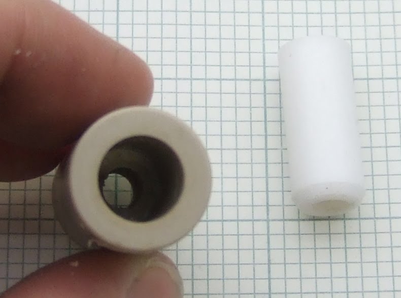
Brian Reifsnyder asked for volunteers to test his hybrid PEEK and PTFE insulator design, so I used it for the hot part of my Mendel extruder to start with. The drive mechanism is Wade's design.
It worked well at first, requiring little force to extrude PLA, but got harder and harder until eventually it completely jammed. This video below shows that even with the nozzle removed and starting with a completely empty barrel I couldn't push more than about 15mm of filament through it.
The reason was that the PTFE liner had slipped a little leaving a small gap between it and the end of the brass heater barrel.
This makes the extruder jam completely solid. The reason is that PLA goes rubbery above 50°C, so any pressure on it makes it expand width wise and grip the side of the tube. If there is a gap that it can expand into it locks the filament.
I stripped it down, cleaned it out and reassembled it with some washers to hold the PTFE down.
Brian has added a circlip to the design to solve the problem.
I haven't tested this version yet because I ran into another problem before it arrived. When I started using a heated bed for PLA the extruder jammed again. This time it was because the top end of the insulator got hotter than the glass transition of the PLA, so it swelled as it went into the insulator and jammed in the tapered entrance. There was also some leakage around the threads.
The reason it got too hot is a combination of the heated bed, the fact that I used an uninsulated heater with a large surface area, and the fact that the Mendel carriage traps the rising heat.
I decided to try out an idea I had a while ago, which is similar in intent to Brian's scheme. Instead of putting PTFE inside PEEK to stop it expanding I put it inside a 15mm copper pipe. This not only totally constrains it so it cannot swell, it also removes heat from it, shortening the transition zone. I am calling this one Plumbstruder. Here is a sketch of the layout: -
The end of the copper pipe is closed off by soldering an end cap on and then drilling it out to leave a lip to support a PEEK disk which the barrel screws into as well as into the PTFE. That means the PEEK supports the extrusion force, as in Brian's design, but I also use the thread in the PTFE as a seal rather than just having a compression joint.
The copper pipe gets hot so I coupled it to a big heatsink with a copper flange.
I turned this from a solid block of copper a friend gave me (thanks Paul). I soldered it onto the pipe and screwed it onto the heatsink.
I turned the one piece nozzle / barrel from hex stock so it has a nut shaped flange in the middle to make it easy to screw in and also gives the aluminium heater block something to tighten against.
I had to turn down the PTFE to be a tight fit inside the pipe. I was hoping to find a size where the ID of the pipe matched the OD of the PTFE. 22mm copper pipe has an ID of 20mm, so theoretically 20mm PTFE rod would fit. In practice I have found that PTFE rod is about +/- 0.5mm so, unless you were lucky, the fit would not be good enough.
Even with a big heatsink it was getting uncomfortably warm so I added a tiny fan.
I have been using this extruder on my Mendel for a few weeks and it is totally reliable, with no sign of leaking. I think that of all the extruders I have made, this one needs the least force to extrude. I can push plastic through by hand at high speed with ease. For an extruder to work I think the transition zone needs at least two of the following three attributes: short, slippery or tapered. Unfortunately a short transition zone seems to mean using a heatsink, which is not ideal for a moving head machine.
I also think a short melt zone improves the accuracy by reducing the start-stop time. In that respect this design is not ideal, although it is no worse than the standard design.
As my MK3 heated bed on HydraRaptor has been working well I decided to scale it up for Mendel.
Buying aluminium that is flat seemed to be a hit and miss affair until a friend told me that what I need is tooling plate and put me in touch with a company that sells it. They recommended C250 cast machined tooling plate. It wasn't cheap (I got 5 pieces 200 × 200mm for ~ £140) but they are all flat.
I can't find a geometric definition of flatness. It is given as +/- 0.4mm for a 6mm sheet of C250 (I would have preferred 5mm to reduce the mass a bit but that is +/- 0.8mm). I take it to mean that all the points on the surface of a metre square plate will lie in a volume 0.8mm high. For a 200mm piece I expect the deviation to be about 1/5 of that, i.e. 0.16mm assuming it is a single curve rather than wavy. Since the bed can be levelled at the corners the deviation in the middle should be about half that again, 0.08mm, just about acceptable for raft-less printing.
When I tried levelling the bed I ran into a problem though. With my Dibond bed I could level each corner because it can flex a bit. With the rigid aluminium bed I can only level three out of the four corners at a time. When I move the nozzle to each corner in turn it behaves as if two diagonally opposite corners are lower than the other two. That would imply the plate is not flat, but I know it is when I put a straight edge across it. I think this means that the two y-axis bars are not quite level with each other at both ends, causing the bed to twist about the y-axis as it traverses it. I expect it could be corrected by adjusting the frame but I haven't got my head around what to adjust and in what direction yet.
Given that I am using 188W on a 150mm bed on HydraRaptor, to get a similar warm up time I would need 335W. That seems a lot to get from a PSU, so I decided to make it mains driven. I found that I could get 47Ω TO220 resistors cheaper than other values. Five in series across the mains gives about 250W, so I used two strings of five to give 500W. That gives a warm up time of about three minutes.
Equally spacing four or nine resistors on a square is easy but placing ten is an interesting problem. I used the solution to packing ten circles in a square that I found here. This is my layout with 16 magnets as well.
And here it is wired up: -
I used wire with PTFE insulation rated to 300°C. I have an earth connection of course. It would be a good idea to have a second earth in case the first one breaks due to the constant bed movement. I also fitted a 150°C thermal cut out that came out of a microwave oven. With 500W it would get very hot indeed if the control circuit failed.
I intended to mount the magnets the way I did before, by drilling holes not quite through, leaving a rim to retain them. I didn't tighten my drill stop enough and went all the way through so I decided to glue them in with JB-Weld.
I placed the bed onto a sheet of glass with some cling film on it. I then dropped in the magnets and glued them. When I turned it over the next day I found the magnets were sticking up from the surface. The glue must expand as it sets pushing the magnets down and lifting the plate!
I tapped them down with a punch but, unsurprisingly, they fell out the first time the bed was heated. In the end I jammed them in with PET tape. Drilling part way through is a much better solution.
I mounted the bed on top of the Dibond bed with nylon stand-offs.
Not an ideal solution as a lot of z-travel is lost, but the thermal cut-out is quite deep.
I used chocolate block connectors to wire up the mains. To make them safe and provide strain relief for the cables I RepRapped some plastic covers.
The lids just clip on with some tabs that fit into small slots. They didn't fit very tightly, I need to make the tabs bigger and a tighter fit. A boss and a screw hole would have been better I think.
For safety all the wires should be inside the cover as everything accessible should be double insulated. I will make it wider at my next attempt.
The bed worked well for the first few objects I made. Simple bang-bang control gave about 10°C overshoot initially but settles down before the object build starts so does not really matter. One thing I have realised is that the nylon pillars expand about 0.1mm when they warm up so I give them some time to do that otherwise the first layer has varying height.
I got some new ABS from reprapsource.com that turned out to be white, I was expecting natural as that is easier to work with. It seems to need higher temperatures to get it to stick to itself and the bed. I am extruding at 240°C with the bed at 140°C for the first layer and 110°C after that. I built one object like that and then disaster struck. The bed heated to 140°C and levelled off. While the extruder was heating I heard a few pops and crackles. When I looked at the temperature graph I saw the bed temperature soaring. Before I had time to think what was happening there was a loud bang and flash from underneath the bed and the 5A fuse in the plug blew.
What happened was one of the resistors developed a short between its tab and one of the connections. That caused a path to earth which increased the power on the remaining four in the chain. Several of those went short circuit as well in a chain reaction which ended up shorting the mains.What I couldn't explain at first was why the firmware did not turn it off and why the thermal cut-out did not cut the power. It turns out that I had swapped the live and neutral connections in the IEC connector, which meant that the solid state relay and the cut-out were in the neutral connection. As soon as the first resistor shorted it had bypassed all the control, not good!
I had originally chosen the resistors when I was making a bed for PLA at 60°C. Looking at the datasheet they have a maximum operating temperature of 155°C but they are de-rated to zero wattage at that temperature, so by putting 50W into them at 140°C I am grossly over loading them. I have abused AL clad and vitreous enamel resistors in this way and not had any problems but the TO220 seem far less robust. I don't know what they use for the tab insulation but I wouldn't be surprised if it was epoxy. The high voltage may also have been a factor as the ones on HydraRaptor have survived a similar overload so far. They have the same de-rating curve, but are made by a different company.
I rebuilt the bed and changed my firmware to stay inside the power curve by reducing the PWM ratio as the temperature increases. Unfortunately , I found I could only get to 130°C so I had to change the zero power point to 200°C to get to 140°C in a reasonable time. Even then it takes 400 seconds instead of 175.
So far it is holding up, but it is nowhere near as fast as I wanted. A shame because I had bought 50 of the 47Ω resistors, but I think I will have to scrap them and go back to AL clad. The smallest ones that I have used before are not rated for mains voltage so I will need some bigger ones. PCB or stick on silicone heaters are starting to look more attractive!
I find ABS sticks to Kapton very well to start with, but as it ages, it seems to stick less well. Corners start to lift and eventually builds are ruined. I have tried cleaning it with isopropyl alcohol and with acetone but it makes no difference. Charles Pax has reported that sanding with 220 grit paper makes it stick better. I cannot reproduce this. In fact, I find the opposite effect. It always sticks well when new, and if anything, sanding it makes it worse.
Somebody pointed out a while ago that you can get PET tape that is rated to 250°C. That is not as high as Kapton, but just about adequate for a heated bed when extruding ABS at 240°C.
I bought some and when my Kapton stopped working I decided to give it a try. It seems to work well. The first layer goes down perfectly :-
and the objects stay flat: -
I do the first layer at 240°C with the bed at 120°C and subsequent layers at 220°C with the bed at 110°C. I have made all the parts for an extruder on it so far and it has performed perfectly. The extruder will be on eBay this evening.
It is too early to say if it better than Kapton, but it looks promising.
I had been making Mendel parts with my Mendel, using PLA on blue masking tape, as it didn't have a heated bed . When I made a frame vertex on its own it came out completely flat. Larger parts like the z-base brackets warped a little at the corners, but were still acceptable. However, when I made a bed full of parts the warping was much worse. Frame vertexes warped a little and z-base brackets curled up several millimetres and jammed the y-axis, ruining a bed full of parts. I think the reason they warp more is that it takes so long for each layer that the parts are completely cold when the next layer is deposited. The odd thing is that Adrian Bowyer manages to print trays full of parts on blue masking tape without a heated bed. I have added it to the growing list of things that work better in Bath than they do here: AOI and PTFE being another two.
I had some aluminium plate on order but I wanted to knock something up quickly. I figured PLA on blue tape would only need 40-50°C to stop it warping. My bed is made from Dibond, which is 3mm thick and has the following characteristics:
The great thing about it is that it appears to come pretty flat and is strong, light and easy to machine. I wondered if the aluminium layer was thick enough to spread the heat. I didn't think heat would flow though the LDPE very well so I mounted 10 47Ω 50W resistors around the top edge. I have found that for some reason 47Ω are cheaper than the 12Ω ones I used on HydraRaptor's bed. I wired them in pairs in series and then all the pairs in parallel giving 18.8Ω. I connected them to my 48V AC transformer with a small solid state relay. The total power is about 120W. Not as much as I use on my aluminium beds, but plenty of power to get to 50°C quickly. In fact, it warms up faster that my extruder does.
An initial test showed that the middle was about 10°C cooler than the edge. Not a big surprise considering how thin the aluminium is and how far the heat has to travel. When I measured the other side the difference was only about 5°C, so I decided to mount it upside down with the resistors on the bottom and the thermocouple on the top.
It works very well, and the objects stay flat. The first multi-part build I did though failed after the first few layers.
The extruder jammed because the top of the thermal insulator got hot enough to allow the PLA filament to go soft before the entrance. The extruder was finding PLA very hard to push anyway and the maximum speed I could get was about 24mm/s of 0.5mm filament. This is because the thermal transition zone is too long. The extra heat rising from the bed must have pushed it over the edge, literally!
The insulator is a combination of PTFE for slipperiness and PEEK for strength, but I think PEEK conducts too much heat. It doesn't help that my heater is not insulated yet and the Mendel carriage traps any rising heat.
I am quite happy with with Wade's drive mechanism but decided it was time to try another hot end design, coming soon ...
I think that for PLA, Dibond and blue tape / Kapton is a good solution. It won't handle the temperatures for ABS on Kapton though, but it might be good for ABS on PMMA or PC.
Vik Olliver asked for a volunteer with a heated bed to see if we can extrude onto copper clad board. I didn't think it would stick, but gave it a go anyway.
I first tried ABS onto double sided copper clad FR4 taped to a bed at 120°C. The ABS stuck well enough to extrude the first layer of a 20mm square, but when it cooled down it had no adhesion at all.
PLA at 55°C did exactly the same, but PLA at 130°C stuck very well, so well in fact that I can't get it off with my fingers (the blob was where I aborted the print after the first layer).
Maybe ABS would stick in the same way at an even higher temperature, but maybe not as it is less like glue than PLA. The 120°C / 55°C temperatures are what I use for Kapton, which is why I used them as the starting point.
An interesting aside: I had to measure the PCB to work out the z-height. It is only 1.4mm thick, whereas a standard PCB is 1.6mm. You can also see the grains in the FR4 showing through the copper. This means the board I bought in Maplin for home PCB use is actually the same stock material that they use for the first part of a commercial production process, but when they plate thorough the vias they increase the thickness of the copper all over to get the standard 1oz/inch2. I don't know if this is always the case, i.e, that all home made PCBs have less copper than a production one, or whether you can get bare board with 1oz on it already.
Anyway a good result, assuming PLA will resist PCB etchant. Also, it seemed like a potential bed technique. I.e. do the first layer onto hot copper and then cool it to about 50°C for the rest of the object. I tried it with this butterfly: -
It worked perfectly. After the first layer I blew it with a fan to cool it down to 50°C. It took about four layers to get down to that temperature. Since I added the insulation under the bed it takes longer to cool it than it does to heat it.
After it had finished and cooled down to 40°C it was still firmly attached, so I removed it by flexing the PCB.
The base of the object is perfectly flat.
I think for PLA this might be a better technique than Kapton. I can't imagine the PCB wearing out. It could also be self heating with a serpentine track on the other side. I don't know that just taping it down would be strong enough for making large objects. I could solder fastenings on the back if not.
I don't know if there is anything special about copper and PLA, or whether other hot metals and plastic would work . I tried similar things with ABS on AL, but may not have had it hot enough.
My first heated bed worked OK but it was slow to warm up and hard to remove objects.
The second one was only ever intended for experimenting with vacuums and magnets but I ended up printing most of my Mendel on it. It worked well but limits the build area.
I have now replaced it with a full size version, using the lessons learned from the first two.
The first bed was the same size as HydraRaptor's table (200 × 200mm) but the build area is only about 150 × 150mm. The warm up time and power are both proportional to area, so I made this one just big enough, i.e. 150×150mm. Removing the 25mm border nearly halves the area!
The other innovations were to make it easier to build. I replaced nine AL clad resistors with four TO220 resistors. These are rated at 50W and 155°C, so are actually totally within spec when I run the table from 48V giving 188W. Instead of having to tap two M2 holes for each resistor these only need a single M3 hole. That is much easier to tap as the tap is a lot sturdier.
They are also lower profile of course. I just noticed that 47Ω ones are less than half the price, so I should have used four of those in parallel instead.
The thermocouple is mounted with a clamp made from PTFE.
Since this bed has a steel plate on top none of the holes need to be blind. That makes drilling and tapping easier as well.
On my previous magnetic bed I placed the magnets in blind holes that were almost all the way through. That required a milling machine to get flat bottomed holes. On this version I just drilled almost all the way though, leaving a lip to retain the magnet.
This is the top side. The magnet in the middle was done with an alternative technique. I drilled a through hole and then jammed the magnet in with a few strands of copper wire. That gets it flush with the surface, giving maximum magnetic force, but it pulled through on first use. I will have to glue it with high temperature epoxy I think.
After a suggestion by Enrique that wool was a good high temperature insulator my friend Steve gave me some carpet underlay made from wool. I used it to insulate the underside, thanks guys.
For the steel plate on the top I used the cover of an old CD ROM. It is only 145mm wide unfortunately. I think it is mild steel with nickel plating. Not as good as the stainless steel springy piece I got from inside a toaster.
So here is the finished article with the biggest bit of Mendel built on it. It was quite hard to remove. I had to remove the steel plate and bend it a little as intended. I had found that things I built recently on the small table could be removed without lifting the plate. I think the Kapton gets less grip as it ages. I tried cleaning it with alcohol and sanding it with very fine emery paper, but that seemed to make it worse if anything. It seems that shiny Kapton gives more grip than matt.
I aimed to build my Mendel in time to show it at the Makerfaire in Newcastle but completely failed. I had two weeks to build it, which I thought was plenty. In actual fact it took closer to three weeks before I got it printing successfully. I had no major problems, just a few snags here and there and a severe underestimation of how long it would take on my part.
Printed Parts
Unlike when I printed two sets of Darwin parts, printing the parts was the easy bit. This was due to three breakthroughs I had at the beginning of the year: -
The heated Kapton bed removed the need for rafts, which not only take a significant time to print, but also can take a lot of manual work to remove.
The extruder fast reverse got rid of all the strings, which also took a long time to clean up, especially from inside the Darwin corner blocks.
The "no compromise" extruder is so reliable that I have the confidence to do multi-part, layer by layer builds, which gets a lot more on the table, allowing longer unattended operation.
I printed the parts with 0.4mm or 0.375mm filament and with 25% infill. For the larger parts I used two outlines for strength. Since the large parts don't need fine detail, I think printing them with 0.5mm filament and one outline would be quicker, but that would need a bigger nozzle.
The weight of the parts, not including the extruder, was only 730g. I printed the outlines at 16mm/s and the infill at 32mm/s, so it's hard to say the total time. Assuming an average speed of 24mm/s at 0.4mm diameter gives about 3 mm3/s. That would put the total time at about 65 hours. I did it as a background task over a few weeks. A lot of the parts were printed as experiments with heated beds.
Rods
I took me an evening to cut all the rods. The method I used was to nail a stop to my workbench to line up the rod against a metre rule.
I then lined a piece of masking tape up with the correct measurement and wrapped it round the rod to mark the place to cut. I also wrote the name of the rod on the tape to make it easy to identify later.
A Black & Decker workmate makes an ideal vice to hold the rods while sawing. I rotate the studding until the thread lines up with the edge of the masking tape. That guides the saw to start in exactly the right place.
I used BZP for all the studding except the z-leadscrews, for which I used A2 stainless steel because it is smoother and generally straighter. I bought the rods from Farnell and even the BZP studding was very straight, a lot better than the stuff you get in B&Q. I also used A2 for all the bars.
It was very hard work sawing the A2 until I switched to a new blade and used Trefolex cutting compound. I am not sure which made the most difference, but I could then cut the A2 much easier than I had been previously cutting the BZP. I wish I had done that earlier, it would have saved a few hours.
Thick Sheets
The thick sheet parts are not really suitable for making by hand, particularly the squashed frog. They have lots of slots, which are hard to make without a milling machine or a laser cutter, etc.
I am not sure exactly what the hole in the bed and the purge plate are for, so I made the bed a simple rectangle with four holes. I am using my own electronics, so I made the two circuit board plates to suite. I simply cut rectangles and I marked the holes and drilled them in the right place, so no need for slots. That just left the squashed frog.
I made a much simpler design with drill centres on it. There is no need for the bulging legs and sloping shoulders. I think they must be just to make it look more like a frog. Fine if you you are CNCing it, but a PITA if you have to make it by hand. Also the holes for the opto tab and the purge plate are mirrored for no apparent reason, so I made it chiral.
This just starts as a rectangle with some holes in it. Then the large slots are made with a saw thin enough to turn in the holes. The outer holes that mount the bearings can be round because they are in a a fixed place, dictated by the holes in the bed. The inner holes need to be slots because the bearings are adjustable. I just left them off the template and marked them with the bearings adjusted and in place.
I made the sheets from 3mm Dibond, which is below the recommended thickness, but seems stiff enough. It is also light weight and very easy to machine.
Thin Sheet
I didn't have any optos, so I used micro switches for my end stops, hence didn't need any thin sheet parts. I simply attached them to the bars of each axis with P-clips. A little RepRapped bracket would be better but I was building this in a hurry, so had gone into bodging mode at this point!
They seem to have sufficient repeatability and certainly will when I replace the electronics with my new design, which will know the motor phase, reducing the uncertainty by a factor of 32. It is the same switch that I have used on the z-axis of HydraRaptor, which has proven totally reliable. They seem to be this one from RS, not cheap.
Belts
These were easy enough to split but, because the reinforcing wires run in a spiral, the blade tends to follow one for a while before managing to cut through it. That leaves a ragged edge with a bit of wire sticking out.
I didn't understand the rationale for slackening the belts until you just don't see backlash when moving one motor detent. I am microstepping anyway, so a motor detent is not significant. I made my belts good and tight.
Snags
I had a few snags with the mechanical assembly: -
The x-axis spacers are too short. The STL files are 5mm shorter than the parts in the STEP assembly. That caused the motor to clash with the nuts on the 360 bearing.
The 180 bearing at the other end was about 10mm from where it should be.
A simple fix was to slide the axis along leaving a 10mm gap to the spacer, the only problem remaining is that the spacers rattle at certain step rates.
The STEP model shows this gap should be only 5mm, but I have been unable to find the discrepancy. My rods and inspection distances are correct and the ends of the rods are flush with the clamps, as they are in the model.
The bed springs seemed to be too long to compress to the length of the bed-height-spacer-31mm_1off, which is not actually 31mm, but 29mm, so I don't know what gives there, I just spaced them a bit higher.
The bolts in the z-bar clamps are too long to allow the bearing to be inserted. I replaced them with shorter ones.
Similarly the bolts in the x-carriage get in the way of the extruder I fitted.
The J3 jigged distance did not seem correct. The distance between the y-bars is set by the J2 distance and the 3 nut spacers.
The gears work well, with very little backlash, but the small one has some movement on the motor shaft. It is just a press fit with a flat on the shaft. I need to redesign it with a captive nut and grub screw.
I didn't have a suitable M8 shoulder bolt so I made one from brass by attaching a nut with a pin through it.
I hobbed it with an M3.5 tap. I haven't measured the grip, but I get the impression it is not as high as Wade gets, I am not sure why.
For the bottom half of the extruder I used some parts that Brian was looking for volunteers to test for him.
The insulator is made from PEEK with a PTFE liner. The idea being to get the strength of the PEEK and the slipperiness of the PTFE. It seems to work well with PLA, which is all I have run through it so far.
The barrel is long because it is designed to take nichrome, but I just screwed it into a block of aluminium with a vitreous enamel resistor in it.
This was left over from a previous experiment. I have now moved onto a smaller resistor size, so this block could be smaller. The barrel could be a lot shorter with this arrangement and that would give less ooze and less viscous resistance.
The extruder works well with PLA. The main problem with it is that it mounts at right angles to the x-axis, so the motor severely restricts the maximum height of the z-axis. Another issue is that to remove it you have to remove the motor to get at the bolts. To remove the motor you have to remove the big pulley to get at the motor's bolts, to do that you have to remove the pinch wheel assembly. I.e. to remove the extruder you have to completely disassemble it!
Electronics
To get up and running quickly I used the same electronics that I use on HydraRaptor. The only difference being that I used MakerBot V3 stepper drivers. These use the A3977 chip and give x8 microstepping. That gives an axis resolution of 0.025mm, but more importantly gives nice smooth running.
When the weather was exceptionally dry I found they are very sensitive to static. A discharge to any part of the machine would cause the A3977 to shut down its outputs and draw enough current from the 5V rail to cause the 100mA regulator to current limit. The red LED on the power rail goes dim. Powering off and on again fixes it and there doesn't seem to be lasting damage. I suspect that might not be the case if the 5V rail was not current limited. Apparently the only way to fix it is to add external Schottky diodes. That is very disappointing as one of the nice features of the chip is that it is supposed not to need them. I will investigate further to see if all eight diodes are needed before making my own board.
Firmware
I used the same firmware as HydraRaptor. I just added some compile time conditionals to cope with two pin outs and a different IP and MAC address for each machine. I also had to change from 16bit to 32 bit positional commands because the axes are bigger.
Software
I used the same Python software as HydraRaptor but I had to re-factor it quite a lot to support both machines. I added a class to represent the Cartesian bot which holds the axis resolution, direction, maximum speed and acceleration plus the IP address. I also added a class to represent the extruder controller as I have calibration values unique to each board. I already had classes to represent thermistors and extruders.
I can run both machines at the same time from one PC and, because I only use the Skeinforge output for the toolpath, I can use the same sliced files for either machine. This is despite the fact that they run at different speeds and are loaded with different plastic.
Results
So here is the finished machine: -
And here is a video showing it being tested: -
I am running the X & Y motors at about 0.75A and Z at about 1A. I have set the maximum XY speed to 100mm/s, but I think it could go a lot faster. Z only goes at about 5mm/s because not only is it a threaded rod drive, but it is geared down by the belt and pulleys!
I haven't printed a lot yet, but so far the results look as good as they do from HydraRaptor. The next thing to do is add a heated bed and try ABS.