As my
MK3 heated bed on HydraRaptor has been working well I decided to scale it up for Mendel.
Buying aluminium that is flat seemed to be a hit and miss affair until a friend told me that what I need is tooling plate and put me in touch with a company that sells it. They recommended
C250 cast machined tooling plate. It wasn't cheap (I got 5 pieces 200 × 200mm for ~ £140) but they are all flat.
I can't find a geometric definition of flatness. It is given as +/- 0.4mm for a 6mm sheet of C250 (I would have preferred 5mm to reduce the mass a bit but that is +/- 0.8mm). I take it to mean that all the points on the surface of a metre square plate will lie in a volume 0.8mm high. For a 200mm piece I expect the deviation to be about 1/5 of that, i.e. 0.16mm assuming it is a single curve rather than wavy. Since the bed can be levelled at the corners the deviation in the middle should be about half that again, 0.08mm, just about acceptable for raft-less printing.
When I tried levelling the bed I ran into a problem though. With my Dibond bed I could level each corner because it can flex a bit. With the rigid aluminium bed I can only level three out of the four corners at a time. When I move the nozzle to each corner in turn it behaves as if two diagonally opposite corners are lower than the other two. That would imply the plate is not flat, but I know it is when I put a straight edge across it. I think this means that the two y-axis bars are not quite level with each other at both ends, causing the bed to twist about the y-axis as it traverses it. I expect it could be corrected by adjusting the frame but I haven't got my head around what to adjust and in what direction yet.
Given that I am using 188W on a 150mm bed on HydraRaptor, to get a similar warm up time I would need 335W. That seems a lot to get from a PSU, so I decided to make it mains driven. I found that I could get 47Ω TO220 resistors cheaper than other values. Five in series across the mains gives about 250W, so I used two strings of five to give 500W. That gives a warm up time of about three minutes.
Equally spacing four or nine resistors on a square is easy but placing ten is an interesting problem. I used the solution to packing ten circles in a square that I found
here. This is my layout with 16 magnets as well.

And here it is wired up: -

I used wire with PTFE insulation rated to 300°C. I have an earth connection of course. It would be a good idea to have a second earth in case the first one breaks due to the constant bed movement. I also fitted a 150°C thermal cut out that came out of a microwave oven. With 500W it would get very hot indeed if the control circuit failed.
I intended to mount the magnets the way I did before, by drilling holes not quite through, leaving a rim to retain them. I didn't tighten my drill stop enough and went all the way through so I decided to glue them in with JB-Weld.
I placed the bed onto a sheet of glass with some cling film on it. I then dropped in the magnets and glued them. When I turned it over the next day I found the magnets were sticking up from the surface. The glue must expand as it sets pushing the magnets down and lifting the plate!
I tapped them down with a punch but, unsurprisingly, they fell out the first time the bed was heated. In the end I jammed them in with PET tape. Drilling part way through is a much better solution.
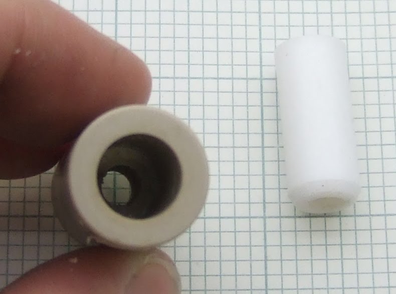
I mounted the bed on top of the Dibond bed with nylon stand-offs.

Not an ideal solution as a lot of z-travel is lost, but the thermal cut-out is quite deep.
I used chocolate block connectors to wire up the mains. To make them safe and provide strain relief for the cables I RepRapped some plastic covers.
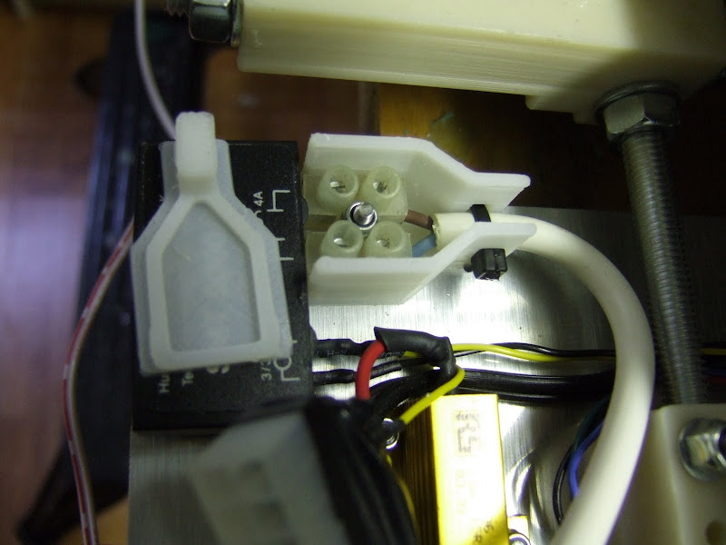
The lids just clip on with some tabs that fit into small slots. They didn't fit very tightly, I need to make the tabs bigger and a tighter fit. A boss and a screw hole would have been better I think.


For safety all the wires should be inside the cover as everything accessible should be double insulated. I will make it wider at my next attempt.

The bed worked well for the first few objects I made. Simple bang-bang control gave about 10°C overshoot initially but settles down before the object build starts so does not really matter. One thing I have realised is that the nylon pillars expand about 0.1mm when they warm up so I give them some time to do that otherwise the first layer has varying height.
I got some new ABS from
reprapsource.com that turned out to be white, I was expecting natural as that is easier to work with. It seems to need higher temperatures to get it to stick to itself and the bed. I am extruding at 240°C with the bed at 140°C for the first layer and 110°C after that. I built one object like that and then disaster struck. The bed heated to 140°C and levelled off. While the extruder was heating I heard a few pops and crackles. When I looked at the temperature graph I saw the bed temperature soaring. Before I had time to think what was happening there was a loud bang and flash from underneath the bed and the 5A fuse in the plug blew.
What happened was one of the resistors developed a short between its tab and one of the connections. That caused a path to earth which increased the power on the remaining four in the chain. Several of those went short circuit as well in a chain reaction which ended up shorting the mains.What I couldn't explain at first was why the firmware did not turn it off and why the thermal cut-out did not cut the power. It turns out that I had swapped the live and neutral connections in the IEC connector, which meant that the solid state relay and the cut-out were in the neutral connection. As soon as the first resistor shorted it had bypassed all the control, not good!
I had originally chosen the resistors when I was making a bed for PLA at 60°C. Looking at the datasheet they have a maximum operating temperature of 155°C but they are de-rated to zero wattage at that temperature, so by putting 50W into them at 140°C I am grossly over loading them. I have abused AL clad and vitreous enamel resistors in this way and not had any problems but the TO220 seem far less robust. I don't know what they use for the tab insulation but I wouldn't be surprised if it was epoxy. The high voltage may also have been a factor as the ones on HydraRaptor have survived a similar overload so far. They have the same de-rating curve, but are made by a different company.
I rebuilt the bed and changed my firmware to stay inside the power curve by reducing the PWM ratio as the temperature increases. Unfortunately , I found I could only get to 130°C so I had to change the zero power point to 200°C to get to 140°C in a reasonable time. Even then it takes 400 seconds instead of 175.
So far it is holding up, but it is nowhere near as fast as I wanted. A shame because I had bought 50 of the 47Ω resistors, but I think I will have to scrap them and go back to AL clad. The smallest ones that I have used before are not rated for mains voltage so I will need some bigger ones. PCB or stick on silicone heaters are starting to look more attractive!