Sunday 1 June 2008

Catalogue of disasters

Last week things were going well. I made this door handle to be exhibited at the Cheltenham Science Festival: -


More details here.

I wrote a script that can print n copies of the same object by spacing them out so that the head can get between them. It would be more efficient to print them closer together, one layer of each at a time, but if anything goes wrong then they are all scrap so I am taking the conservative approach at the moment.

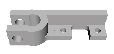
With the script I managed three printing shifts in a day. I set off a batch of seven diagonal tie brackets in the morning and they were waiting for me when I got home from work.


I then printed the X-carriage during the evening and another seven diagonal tie brackets during the night.


My wife thinks it looks like a ruined church and I have to agree.

After that things started to go downhill. The flexible drive coupling broke for the third time, but that was easy to replace by soldering in another piece of cable.


The first thing I made when it was back up and running was an old version of the extruder motor bracket which allows a direct drive. At this point the JB-Weld heater insulation started to fall off leaving the heater wire bare. It seemed to miraculously stay in place and still give heat even when most of the JB-Weld had gone.

I did notice the heater duty cycle was going up, eventually reaching 100%, but that was to be expected as there was less thermal conduction from the wire to the barrel. Then the temperature didn't quite make the set point, but it was close so I carried on using the machine. I made three pulleys but they seemed to get too hot. The top was distorted and they were impossible to separate from the raft. I put this down to them being smaller than anything I had made so far and decided to make something bigger. I left the machine making a bed corner bracket and went out for a walk. When I can back the house stank of burning plastic and the bed corner bracket was impossible to separate from its raft, and the raft was welded onto the bed material.


I finally twigged, the reason the temperature was reading low, and hence the heater was full on, was because the JB-Weld holding the thermistor had also decomposed. I don't know what the temperature was but it was way too high.

So I switched to my Cerastil heater and the nozzle from my high temperature extruder experiment. I also had to replace the bed material as it had a big hole in it where I broke off the corner bracket.

I powered it up and calibrated it and it seemed fine. I left it running for a while and it started making popping sounds and producing little clouds of smoke. Very odd, while I was puzzling over it the temperature reading started falling with the heater on. Then clouds of smoke started streaming out of the extruder.

Aha I thought, the thermistor must have come off again, but when I stripped it down I found it hadn't. What actually happened was molten ABS had escaped from the thread of the nozzle and got onto the thermistor. For some reason that must have cooled it, causing it to read low, so the heater overheated again.

I fixed the leak by sealing the thread with PTFE plumbing tape. I set the machine off again but it only got half way through a raft when the heater barrel escaped from the PTFE insulator and the nozzle buried itself into the brand new bed material.

I made a new PTFE barrel (as the old one had obviously been softened by its high temperature excursions) but when I was reassembling it, the thermistor, which was only stuck with JB-Weld, fell off. So back to square one!

I stuck the thermistor back on with Cerastil but when I screwed the nozzle on it was too close, so it broke off again. Starting to get a bit frustrated now, to put it mildly!

I stuck the thermistor on again with Cerastil, this time after I screwed the nozzle on, but while reassembling the extruder for the nth time one of the heater wires broke off. I was able to dig out the connection and solder to it with high temperature solder.

I reassembled the extruder yet again and set the machine going. Half way through the raft the drive shaft broke, not the flexible bit, but the solid bit it was soldered into!

At this point I started to think I was never going to get a working extruder again. A week had passed, I had been working on it every evening but every time I fixed something, something else broke. I had taken it apart and reassembled it so many times that the threads on the M3 studding that tensions the springs had worn away and had to be replaced.

Rather than make a new drive shaft I decided to go for the direct drive design that is slightly shorter. I soldered a nut to the end of the broken shaft and modified the couping in the lathe to shorten it and give it a taper to clear the filament.


So HydraRaptor gets its first RP part.


I now seem to be back up and running and have managed to knock out several more Darwin parts.

Pulleys and belt clamps: -


The belt clamps are the smallest things I have made, they only take about 4 minutes each.

This is the largest thing I have made, I think it is the biggest Darwin part, the X-motor bracket: -


It takes about 4 hours and uses 37cc of plastic when done with 25% fill. That is just less than $1 worth of ABS at the RRRF price of $20/Kg.

I also made four bed corner brackets: -


I can only fit two at a time on the table: -


I found that the mystery bed material I am using has a glass transition below 100C so I think it is PVC plus a filler. I stick it down with double sided tape but larger objects manage to lift it at the edges so I made a frame to hold it down. It is a sheet of 3mm HDPE laminated with aluminium. I milled the aperture in it using HydraRaptor's milling head. The only problem is it restricts the build area slightly because the biggest milling bit I have is smaller than the nozzle.

So it seems the machine is running reliably again and two of the things that persistently fail, flexible drive cable and J-B Weld have been eliminated.

I also made this coat hook for Adrian Bowyer: -


It is Adrian's design, sliced by Enrique's software, extruded though a nozzle made by Adrian. It took about 40 minutes and used about 8g of ABS costing $0.16.

Tuesday 20 May 2008

Mystery material

The bed material I am using for ABS works very well but the problem is I don't know what it is. My wife bought it for 10p when I was trying lots of things for HDPE and was disappointed when it did not work. She is now delighted I found a use for it as she loves to get a bargain.

It originally looked like this :-


It is about 3mm thick. Most of that is the plastic backing. On the front is printed paper, stuck on with a double sided sticky film and covered with single sided sticky film. This can be peeled off to just leave the back material so both sides of that can be used.

Here is a bit I destroyed developing rafts: -


It will bend a little but then it snaps, as you can see, when I pulled a raft off that was stuck too well.

I normally use this flowchart to identify plastic but it fails with this material because I think it is a polymer with a fibrous filler, possibly paper.
  • It melts with a low temp soldering iron so is not a thermoset.
  • It floats very well but it is not PE or PP, so that is probably due to a filler.
  • It does not burn well and is self extinguishing.
  • It gives black smoke and if anything has a yellow flame.
  • It does not drip.
  • The smoke has some odour but I don't recognise it. I don't know what phenol smells like though.
So perhaps it is PPO and a fiber. If anybody knows where I can buy it from I will be very grateful. It is quite reusable but I expect it will need replacing sometime and other people want to use it.

Monday 19 May 2008

Stepping up production

As HydraRaptor seems to be working so well with ABS I decided to put my high temperature extruder design on hold and go for making a set of Darwin parts in ABS. This is how far I got before my extruder wore out again: -


The flexible drive cable disintegrated and most of the JB-Weld has fallen off.

Using Enrique's Skeinforge slicer I can make very sparse objects that are still strong when made in ABS. I set the infill to 25% but I am not sure exactly how Skeinforge interprets it. The infill lines are not parallel so they get further apart the longer they are. Large voids are very sparse indeed and smaller voids look like 25% fill.


The outer wall is always two filaments thick, one is the perimeter and the other is the ends of all the infill zigzags that meet each other. With 0.5mm filament and a layer height of 0.4mm the filament threads are 0.6mm wide so the side walls are 1.2mm thick. I set the number of solid layers to 3 so the top and bottom are also 1.2mm thick. Skeinforge is clever enough to make layers with some areas 100% fill (where they are less than three layers from the top or bottom or internal surface) and other areas sparse. Very clever stuff, which really speeds up the build process but still gives remarkably rigid and strong objects.

I made four of Darwin's eight corner blocks (taking about 2.5 hours each) but I was unhappy with the amount of warping I got when not using a raft. I decided to develop peelable rafts and reusable bed material, like commercial machines have, before making any more parts. That took a lot of experiments to get right but I now have a workable system for ABS.


The bed material is the advertising board I used for ABS before, but this time I am using the back. Unfortunately I don't know what it is. It is very buoyant in water and self extinguishing if I burn it. ABS bonds to it very well. If I extrude the object directly onto it then it is impossible to remove. If I put down a sparse raft first at a low temperature I can remove the raft with a penknife. It blisters the surface but that does not seem to matter because the raft presents a smooth surface to the object. It just gets a bit harder to remove the raft each time as the surface gets more blistered.

The board is not strong enough to resist the warping on its own so I stuck it to the back of some floor laminate with Evostick contact glue. Even that could not hold the edges down, hence the metal strip.

The first raft layer I put down is a 1mm filament zigzag with a 50% spacing, extruded at 4mm/s @ 200°C with a nozzle height of 0.7mm. Because the layer is so thick and extruded quite flat, it absorbs any surface irregularities and makes the initial head height less critical. Spacing it 50% allows it to spread sideways, if the head is too low, and also allows it to be removed. 100% fill is impossible to remove and the head height becomes critical. If it is a little too low, the filament is wider but there is nowhere for it to go, so it builds up on the nozzle and blobs.

The first layer is far too course to build upon so I put two layers of fine zigzag the other way on top. These are 0.5mm filament extruded at 16mm/s with a layer height of 0.4mm and spaced just wide enough to not bond with itself laterally. That makes it easier to remove from the base of the object. The temperature is raised to 230°C to give a strong weld to the layers below.

Two layers are needed because the first layer has a rippled surface as it spans the wide gaps in the layer below. I put them down on top of each other rather than alternating the direction of the zigzag. That makes them weaker laterally therefore easier to remove from the object with a penknife.

The raft uses horizontal and vertical zigzags so there is no correspondence with the object infill which is at 45°. Again that makes it easier to separate without risk of pulling a thread out of the bottom of the object.

To ensure the raft does not bond too well to the object it is cooled for a minute with the fan. The first layer of the object is then extruded at 8mm/s @ 215°C and subsequent layers at 16mm/s @ 230°C. The temperatures are critical, so depending on thermistor site and calibration, they will vary a bit from machine to machine.

This is what the bottom of the raft looks like: -


And this is the top: -


It does slow the build and waste plastic but it reduces warping and makes the bed reusable over and over again. I expect it won't last forever but you can certainly use it many times.

The base of the object is also pretty neat and tidy: -


Here are the stats for the objects I have processed so far: -

Seconds Filament @ 16 mm/s Moves @ 32 mm/s Build time Plastic volume Quantity required Total build time Total plastic
Corner bracket @ 25% 8866 122009 mm 34926 mm 02:27:46 24.0 cc 8 19:42:08 191.7 cc
Opto bracket @ 50% 1200 15902 mm 4661 mm 00:20:00 3.1 cc 3 01:00:00 9.4 cc
Diagonal tie bracket @ 25% 2178 31236 mm 3716 mm 00:34:28 6.1 cc 20 11:29:28 122.7 cc

I will update this table as I progress to make the Darwin parts.

Tuesday 6 May 2008

Swiss cheese

HydraRaptor made a Darwin corner bracket in 50% filled ABS this evening: -


It took 2 hours 35 minutes. It feels pretty sturdy but there is some delamination through the thin section of the corner facing the camera. A bit of a weak spot in the design I think. Also the base is a bit warped as I didn't use a raft. I don't know if these matter as I haven't worked out what all the holes are for yet. I need to make seven more for a Darwin. I will probably do a 100% version for comparison.

Monday 5 May 2008

Cat's cradle

I hit another milestone today: HydraRaptor made the first part that I designed myself, using the ArtOfIllusion application. It is the first time I have done any 3D modeling and it is much harder than I thought it would be.

Adrian Bowyer has written a set of hints and tips here and I needed to use every single one of them. I don't know how anybody can use ArtOfIllusion without his guide.

The reason it is difficult is that you have to build up complex 3D shapes by composing primitive shapes like blocks and cylinders with boolean operations like union, intersection and subtract. That is fine but you are not allowed to do boolean ops between objects that have coincident or tangential faces. If you do, then you create non manifold objects which cannot be converted to STL files. However, you generally do want join things with a common faces. Here is the object I designed :-


It is a cradle to support the heatsink of my high temperature extruder design. If you take one of the upright legs as an example you see it's a cylinder that meets a rectangular lug with a common face at the bottom and tangential joints at the sides. It also meets the cone on the top with a common face. All of these are not allowed: I had to make the cylinder slightly too long and slightly bigger in diameter before unioning it with the cone and the block. That left it protruding slightly at the bottom, which is solved by subtracting a large flat rectangle from the base.

Another problem is that if you have long strings of boolean operations the application becomes very slow doing anything. That is solved by converting the results of boolean operations into triangle meshes. It solves the speed issue but then for some reason boolean operations on the resulting triangle mesh only offer intersection and subtraction. To restore the possibility of union you have to optimise the triangle mesh in the solid editor. Not hard, but not intuitive and very time consuming.

I tried to make the object in HDPE with my lash up stainless steel extruder but it was not reliable enough. This was the first attempt which stopped short due the filament slipping in the pump: -


I also realised at this point that two of the columns were too close to the heatsink. Other attempts resulted in either the filament slipping, or the GM3 clutch breaking free. I had stuck it with super glue, but that does not hold very well, so in the end I welded it with my soldering iron.

It takes an enormous amount of force to extrude with the stainless steel barrel and I am beginning to think the idea may be fatally flawed. I think that because there is a slow temperature gradient down the barrel you have a point where the filament is only just molten so it is very viscous, so is hard to push past that point. With the PTFE barrel the temperature will fall away quicker and the walls are also much more slippery.

I will try again with a much shorter barrel, but to get the object made, I put my old extruder back together and made it in ABS: -


As you can see lots of stringing due to extruder overrun, but easily cleaned up with a penknife and drill. It is much easier to remove strings from ABS and HDPE objects than it is from PCL.


I think the dark lines on the posts are grease from the extruder bearings.

All in all I think it worked very well: this is my first ABS object, other than test blocks, and it is also the largest and most complex object I have made so far. It is a bit warped underneath because I didn't use a raft and it is 100% filled. As it happens the underside does not matter at all for this part. It took just over 2 hours so I went for a walk and left it to it.

I designed the shape for HDPE, the objectives are for it to hold the heatsink rigidly and not restrict the airflow too much. Had I designed it for ABS I would have made it a bit less chunky.

Here it is with the heatsink installed: -


Next I need to make a new extruder support bracket / clamp to mate with this part to continue my attempt to make the high temperature extruder.

Saturday 3 May 2008

Experimental extruder

I want to see how much of the Darwin design I can make out of HDPE as that is the plastic I have the most of and is the easiest to get hold of. It should also be the cheapest but I think I got a very bad deal with mine.

To extrude HDPE quickly, without losing accuracy, requires a fan blowing on the work piece while extruding at around 240°C. The PTFE insulator in the extruder starts to lose its strength under these conditions and it also extends about 0.5mm due to thermal expansion. The JB-Weld heater insulation also degrades rapidly. To address these problems I am working on a design using stainless steel as the insulator, which I first blogged here. Here is a second lash up I made to progress the idea :-


At the bottom is a brass nozzle made by the man himself, Adrian Bowyer, and is described here. It has already been superseded with the anti-ooze design shown here.

Above that is a brass barrel that came from BitsFromBytes, with my experimental Cerastil heater on it. I attached a thermistor to the barrel with JB-Weld.

The brass barrel is screwed into the end of a 1/4" stainless steel tube. The other end has been tapped with a 1/4" UNF thread and screwed into a small north bridge heatsink from a PC motherboard (40 x 40 x 15mm). I drilled through the centre and tapped it. To lock it in place and give a good thermal connection I made a square nut from a piece of 10mm aluminium bar. I spread heatsink compound on the threads.

The top of the stainless steel tube is screwed into an old PTFE barrel to join it to the pump. The barrel had swollen so that it wouldn't hold an M6 thread anymore, but fortuitously it seems to have swollen just enough to match 1/4" UNF.

This is by no means the final design, it is far too long and flimsy, it's just to test the concept using existing parts.

I also wanted to try insulating the barrel and nozzle with PTFE. I made an end cap that fits over the nozzle by plunging an 8mm end mill into a 12mm PTFE rod :-


The idea of this is to keep the fan wind off the nozzle and also give it a non-stick surface so that when filament curls upwards and will not stick to it. I also insulated the stainless steel tube with a piece of 12mm PTFE rod with a 7mm hole drilled through it. Here is the completed assembly :-


The gap in the PTFE where the heater and thermistor are and where the wires emerge is covered with fiber class wool. I hate the stuff, I only have to think about it for it to make me itch all over. It is a much better insulator than PTFE though, but I wanted something smooth and slender to not disrupt the airflow from the fan too much.

The wires are sleeved with PTFE insulation and then plugged into a floppy drive connector. So everything at the hot end is good for about 300°C.

How well does it work? Well it took me a long time to be able to get it to extrude HDPE semi reliably. Thermally it works well. With the fan off and the barrel at 250°C the heatsink only gets to about 45°C, easily cool enough to mate with HDPE, ABS and probably PLA and PCL as well. With the fan blowing it cools down to room temperature. The heater power goes from about 60% to 80% so the insulation works well enough. A better idea might be to lag the pipe with a thin layer of fiberglass wool and then wrap it with PTFE baking parchment to give it a smooth outer surface. Or maybe an outer metal pipe with fiberglass in between.

Mechanically it is not that great. It seems to a need lot of force to extrude. I had to open up the hole in the nozzle from Adrian's 0.4mm to my standard 0.5mm. I also had to up the temperature to 250°C. I think this is mainly due to where I am measuring it and how I calibrated the thermistor. Previously I measured the nozzle temperature and calibrated it with a thermocouple inserted into a hole in the nozzle. With this version the thermistor is in a notch on the surface of the heater barrel and I calibrated it with a thermocouple inside the empty barrel. Looking at the value of beta that I got I think that it is considerably hotter inside the barrel than the thermistor is outside. I am not sure how this is. With the heater on the outside of the barrel I can't see how the inside could be hotter. Perhaps the thermal connection of the thermistor to the barrel, via JB-Weld is not as good as it it could be. When sited in the acorn nut nozzle it was half buried in a hole.

Even with the nozzle removed it is quite hard to extrude 3mm filament by hand. Part of this has to do with how long the total barrel is and the fact that it has three joints. The inside of the stainless steel barrel is not as slippery as the PTFE. It might also be the case that the molten section extends further up the barrel causing more viscous friction. I plan to shorten the whole thing considerably: I will combine the clamp with the right angle bracket and take the tube right up to the base of the pump. I will support the heatsink with a cradle structure resembling an upside down table. More importantly, I will shorten the heater barrel by combining it with the nozzle and screwing the tube into it. Making it from aluminium, which is two and a half times a better conductor than brass and easier to machine, should make it easier to get a consistent temperature measurement.

As there is a continuous temperature gradient down the stainless steel, the point at which the plastic melts will be about halfway up so I think the heated nozzle can be quite short indeed. The limiting factor is how long it takes the heat to get to the centre of the filament with the very poor thermal conductivity and high specific heat capacity of the plastic.

Here is an HDPE version of the opto bracket with my best PCL version behind :-


I have no idea why it is so grey. It is not as neat as the PCL one but most of the errors are due to blobs forming when the extruder moves between extruding. These cause the nozzle to be displaced sideways when it gets close because it is so flimsy. Shortening it and supporting it properly will improve matters for sure. I also need to incorporate Adrian's anti-ooze valve somehow.

Monday 21 April 2008

Fun with Python and G code

The current RepRap host software is a monolithic Java program that imports STL files, lets you place the objects to be made on the table, slices and dices them and controls the machine.

In my opinion the slice and dice code should be a separate program from the machine controller. Its inputs should be the 3D model in STL format plus the filament dimensions and the output should be an XML file with extruder paths grouped into layers, outlines and infills. The machine controller then reads the XML and controls the speed, temperature, fan, nozzle wiping, cooling delays, etc, according to the selected material and the machine characteristics. A third layer of software should be the communication protocol to the slave device, e.g. SNAP or G code over serial, USB, Ethernet, etc.

I have moved a little way towards that model by making my machine accept G code from the RepRap host or Enrique's Skeinforge script. I throw away most of the G codes, looking at just enough to build be an internal representation of the extruder path. This is simply a list of layers, which are lists of threads, which are lists of points. From that information I can control my machine, make animated GIFs or preview the paths in a GUI. All of this is trivial in Python.

Here is my first cut at the preview GUI: -


The preview shown is from G code generated by the RepRap host, and here is the object it made: -


Behind is the same object made from G code generated by Skeinforge.bsh. The RepRap one has sharper corners and the infill is a bit better but the Skienforge one is faster to produce because it has sparse infill.

Here is a video of it being made: -


Here is my first attempt to make Vik Olliver's shot glass: -


When it got to the stem the fan could not get the heat away faster than it was arriving and the whole thing became a molten mass. I fixed that by slowing down the extruder to 8mm/s when the layer gets small: -


It took five hours to process with Skeinforge and an hour and a half to build. I couldn't get the RepRap host to process it.

Wednesday 16 April 2008

Python & Beans make object

Having got bored of making rectangular blocks for months I decided it was time to hook up my machine to the RepRap host software so that I could make arbitrary 3D objects from STL files. My original plan was to hack the host code to replace the serial comms with Ethernet and cope with the differences of my machine from the RepRap Darwin. Zach Smith added a G code back end so I decided to just add a G code parser into my Python to save me having to modify the host.

In the meantime Enrique Perez published a plug-in script called Skeinforge.bsh for ArtOfIllusion that also converts 3D objects to G code extruder paths. It is written in the Beanshell script language, which is Java like. I decided to try both approaches, as in theory a G code parser would allow me to use either.

Enrique posted some new scripts that process G code and drive the RepRap hardware using a Python SNAP protocol driver written by greenarrow, so I didn't even need to think about writing a G code parser, I just cut and pasted a few lines from Enrique's.

Before letting it drive my machine I thought it would be a good idea to look at the paths on screen. I knocked up a little script which used my HydraRaptor simulator to draw them. The script is just a few lines of Python that use TkInter.

It was soon apparent that Enrique's code had a bug that left off some of the outline, but apart from that it looked very promising because it has the ability to do sparse infill. That speeds up building objects, saves plastic and reduces warping so it is very worth while. Not only that, it had a novel infill pattern. Instead of parallel lines like this: -


He moves the ends together so that the outer wall is stronger: -


This looks like a good idea because it makes the outer wall effectively two layers thick but probably gives a bit less warping than a second continuous layer would give.

In order to communicate the results to the forums I came up with the idea of making an animated GIF showing all the layers in sequence. This turned out to very easy using Google and Python. The Python Image Library (PIL) can make GIF files and I found a script called gifmaker.py which takes a list of images and uses PIL to calculate the deltas and write out an animated GIF.

Enrique fixed the bug very quickly, here is the sliced extruder pump body: -


The red lines are moves without filament flowing (ideally) and the each new section of filament is a different colour.

And here is the same object sliced by the reprap host :-


A side effect of Enrique's algorithm is that the corners get rounded, however I don't think that matters too much because the filament has a minimum bend radius anyway. The main downside is that beanshell script is very slow, so it takes longer to slice than it does to extrude at the moment. A faster PC will probably sort that.

The first object I tried to make was this opto mounting bracket from the RepRap Darwin: -

I choose it because it is small, so does not take too long, but reasonably complex with a horizontal hole. Here is the sliced path from Enrique's script: -


And here is my first attempt at making it: -


This is PCL extruded onto MDF, 0.625mm filament extruded at 10mm/s with the fan on, no interlayer pauses.

A bit hairy due to the extruder not being able to stop the filament flow quickly, but I was quite pleased with it for a first attempt. It is too tall due to a bug in my code and its not the latest version, which has teardrop shaped holes to make the overhangs less than 45°.

Here it is cleaned up a bit: -


It is 50% filled which is probably not appropriate for this size object in PLA but that part is fully functional I think.

Enrique was pleased to see it as he doesn't have a machine to test his code with. A perfect partnership, he writes all the hard bits in beanshell script and I write the easy stuff in Python!

Thursday 10 April 2008

Basket case

I was using two old component spools to hold my feedstock, see all-wound-up, but I don't have any more so now that I have four polymers I decided to give Vik Olliver's design a try. It has the advantage that you don't have to spool all the filament on, you can just drop in an open reel if that is how your filament comes.

This is my take on it: -


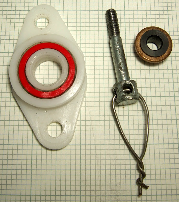
The uprights are 15x15mm aluminium angle. The beam across the top is a piece of 20x10mm channel. The bearing is a standard ball bearing and I reduced its internal diameter with a couple of bushes I had lying around. I then used a bolt with holes through the head as an axle. I found it in the road while I was on a walk wondering what to use. That is the third piece of HydraRaptor that I have picked up in the street.


The baskets are £4.21 in B&Q and have a plate in the bottom with a central hole just right for feeding the filament through. As the machine pulls the filament from the centre of the reel, the basket rotates to prevent it becoming twisted.

It works very well and has the advantage I can buy as many baskets as I have plastics and just take them on an off as needed.

It also allows the filament to rotate in the extruder but ironically, since I tweaked my extruder, PLA no longer feels the need to rotate. Presumably it rotates if the friction between the screw and the plastic is higher than between the plastic and the filament guide. I think that gives a clue to which of my tweaks made all the difference in reducing the extruder torque needed. I think it was adding the washers to space the top of the pump apart so that the screw bites in progressively and sharpening the screw thread.

More PLAying

The tweaks I made to my extruder dramatically improved its ability to extrude PLA. I am not sure which one made all the difference or whether they are all needed. I can now extrude at my target 0.5mm filament 16mm/s with about 75% motor PWM duty cycle. That is less than I needed for ABS before the tweaks.

I can also extrude at lower temperatures. I think 180°C is a bit on the hot side as the plastic is very runny at the temperature. It will flow out of the extruder under gravity and has negative die swell. At 140°C it behaves more like the other plastics and swells to 0.6mm, which is very low.

In a previous article I stated that I could not make sparse filled objects because the filament slumped too much. With the reduction in temperature and increase is speed I now can. Here is a 50% filled block: -


It is still very strong. I expected the warping to be less but I have switched from MDF to balsa and I think that increased it. The balsa I have is only 2mm thick and was only stuck down with masking tape. I might try gluing two pieces back to back with the grains at right angles to get it stiffer.


So now with a slightly tweaked extruder I can do PCL, PLA and ABS at 0.5mm @ 16mm/s. I had to slow down for HDPE to prevent thermal damage to the extruder.

To get good definition at high speed I extrude with a fan running. The fan cools the nozzle which causes more heater power so the barrel temperature rises to the point where PTFE goes soft and the JB Weld turns to dust. PCL and PLA are no problem because the temperature is less. ABS does not seem to need the fan.

I plan to make a PTFE cover for the nozzle which will probably insulate it well enough and hopefully stop filament sticking to it and burning.

Tuesday 8 April 2008

Fantastic PLAstic

I have managed to get the GM3 to extrude PLA reliably with the following tweaks: -
  • I locked the clutch as per Solarbotics instructions.
  • I lubricated the GM3 with silicon grease as per Adrian Bowers suggestion.
  • I sharpened the thread a bit with a half round file following Vik Olliver's instructions.
  • I spaced the top half of the pump slightly further apart with some thicker washers. That gives the thread a gentle lead in.
  • Plenty of oil on the filament.
  • I throttled back the flow rate to 3/4 of the rate I normally use (Ï€ mm3/s).
The motor runs warm, but not alarmingly so. For some reason the filament is no longer rotating in the extruder.

My first attempt curled away from the MDF bed so I used 2mm balsa wood as Adrian has been using for PCL. That worked well so it's good that we can use it for both. I have yet to try it with HDPE and ABS.

I made my standard test block with 0.5mm filament extruded at 180°C (at the nozzle), layer height 0.4mm, pitch 0.6mm, fan on constantly. The results are excellent: very good filament compliance, i.e. sharp corners and flat sides, excellent layer bonding.

It is slightly more warped than my first test. That is probably because balsa is softer than MDF.


No warts on this one!

Monday 7 April 2008

Locking the Solarbotics GM3 clutch

All the adverts for the Solarbotics GM3 gearmotor say the clutch can easily be locked but don't say how. I emailed them today and got a quick reply from Dan: -
Locking the clutch is actually very easy... we should make an effort to get the instructions on-line. All you have to do is glue the little plastic clutching mechanism in its cavity, but to ensure a good contact you should first wipe it out with rubbing alcohol to get the grease out, then score the surface up a bit with the tip of an Exacto knife and then you can use either super glue, model cement, or epoxy to lock it.
So that is what I shall try next to see if i can get it to extrude PLA without warts.

Sunday 6 April 2008

A day with PLA

Adrian Bower has kindly given me a small sample of polylactic acid (PLA) filament to evaluate and some parts to make the new geared extruder are on their way. Being a bit too impatient I decided to try extruding it with my current extruder.

Each polymer I have tried so far (HDPE, PCL and ABS) has had very different characteristics and PLA is very different again. At room temperature it is very hard and brittle and is completely transparent. At somewhere between 50-80°C it has a glass transition temperature above which it becomes a rubbery jelly. If you put it in boiling water and then pick it out with tongs you can bend it as much as you want and when it cools it will set in that shape. These are the two bits of 3mm filament I showed earlier when I had bent a 150mm piece double and it snapped :-


After dipping them in boiling water I could tie knots in them but I had to be quick because it hardens in seconds. If I return them to boiling water they untie themselves and return to being a straight rod.

PLA melts at about 175°C, the highest of all the polymers I have tried so far, where it transitions from jelly to a liquid with the consistency of a thin syrup. If you extrude it quickly into mid air it sets almost instantly and forms a filament, but if you extrude it slowly it forms drops that drip from the nozzle like water from a tap, but are solid when they hit the deck. Very different from HDPE and ABS which extrude more like a paste. Like PCL, PLA is sticky when molten so it sticks to MDF quite well, unlike HPDE and ABS.

Getting it to extrude from the original extruder is next to impossible, I really should have waited for the gears. The problem is that the extruder pumps the filament by cutting a thread into it. PLA is so hard that it needs an enormous force to press the thread into its surface. That is no problem with the springs I have, but it also seems to have a high coefficient of friction, so the torque required to turn the thread is then too much for the GM3 gearmotor and its clutch slips.

Recently I had an idea to cut the torque requirement by shortening the thread. The reasoning goes like this: -

A substantial part or perhaps most of the force required to push the polymer is not the extrusion pressure but the lateral friction of pushing the filament through the filament guide and the tangential friction of cutting the thread. Both of these are equal to the respective coefficients of friction multiplied by the force exerted by the springs. But the force required to achieve enough pressure to push the thread into the plastic must be proportional to the length of contact. So once you have enough thread to push the filament without shearing off, any more is counter productive. It requires more spring force, which creates more friction, which makes the filament harder to push, a vicious circle.

Ian Adkins put the theory to the test and reported he could still extrude PCL with only 7mm of thread. The motor current dropped from 240mA to 190mA. The no load current was 62mA so that indicates about a 50% reduction in torque required. Not being as brave as Ian, I reduced mine a bit less radically to start with. I roughly halved it: -


I used a couple of washers at the top set of screws to space the pump halves apart, to keep them parallel, and just tightened the bottom pair of springs. That did reduce the torque required but even with plenty of oil the GM3 clutch was still slipping. It is a good modification because you save two springs, hence two less adjustments, and the extruder is quicker to strip down and rebuild. Plus future versions of the pump can be made much shorter.

All the adverts for the GM3 say the clutch can easily be locked but don't say how. I opened the gearbox and found the clutch is inside the last gear wheel. I tried putting some bits of thick wire into it to stop the springy bits from compressing.


That worked for a while until one fell out. I thought they would be trapped by the lid but seemingly not. My next attempt was to stick them in with super glue. That worked but the clutch still slips somehow.

Another issue with PLA is that the filament likes to rotate in the pump. Other polymers do that as well, but if you hold them so they can't rotate they still extrude. With PLA, if you don't let it rotate it slows down the motor. Presumably by letting it turn it removes the tangential friction leaving only the sliding friction. The problem with letting it rotate is that I think it means the forward motion is less so the extrusion rate is not what it should be.

When the clutch slips it jumps one notch. Because my shaft encoder is on the output shaft the firmware makes up the difference. If it does not happen too often I still get the right volume extruded. It does however cause a shock wave which makes a blob in the extruded filament. I decided to try and make an object anyway with it slipping occasionally.

Because I only had 8m of filament I decided to try a sparse filled object first. That does not work with PLA because the unsupported filaments sag: -


However, this messy object has a perfectly flat base so shows some promise.

Next I tried a 100% filled block, extruded at 180°C (at the nozzle) 0.75mm filament at 8mm/s, layer height 0.6mm, pitch 0.9mm, fan on continuously. A bit slow and course compared to my other tests but I always start slow and move up in speed.


During this build the clutch started slipping once or twice per revolution causing the warty surface. Near the end it started slipping continuously so this is only about 18.5mm high rather than my standard 20mm test. Never the less, it only has 0.19mm warping after more than 24 hours making it the least warping yet for a solid object. Added to that it is probably the hardest material of the four.

PLA's main downside is the low temperature at which it goes soft, not much better than PCL, even though it has a much higher melting point. In this respect it is very like PVC which also has a high melting point and a glass transition around 80°C.

Here is my warped league: -


I think I can explain why plastics are good and bad for warping. It is simply how much they contract between the point they go solid and room temperature.

HDPE has a high freezing point and high thermal coefficient.
ABS has a slightly lower freezing point and a low thermal coefficient.
PCL has a very low freezing point.
PLA has a glass transition point not much higher than room temperature.

If the object can be stuck to a rigid base while it is cooling then the warping is reduced.

My theory of needing to extrude at twice the melting point minus ambient certainly does not hold for PLA, otherwise I would need to extrude it at 330°C. I get very good bonding at 180°C. It may be that if I extrude very fast it would need to be hotter but I expect it would decompose at 330°C. It may be that the glass transition makes the theory invalid or maybe it is plain wrong. It does seem to be true for polymers which are paste like and not sticky, i.e. ABS and HDPE. PCL and PLA are both sticky when molten. I.e. they will stick to things like glue does whereas HDPE will only weld to things like itself. It has no adhesive quality.

I haven't entirely given up with making the non geared extruder work with PLA. The problem with the geared version is that it can't keep up with my extrusion speeds. I can try reducing the thread even more. I can try sharpening it as Vik Olliver has done. I can find a solution to locking the clutch. The motor does get quite hot so it probably won't last long. I do have three more to burn through before I find a better motor. They only seem to last a couple of weeks in my machine anyway.

Wear and tear

Half way thorough my evaluation of PCL the extruder's flexible drive coupling started to break up again. When I moved to ABS that was the final straw: -


The first one I made was only 2.5mm cable. This was a 3mm one from BitsFromBytes. I replaced it with some 3.2mm cable from B&Q. I drilled the hole out to 3.3mm so it is a snug fit. I also soldered it while it was held in alignment by my lathe so it is very straight.

I think the force required to bend a cable goes it with the fourth power of its diameter so this one is considerably stiffer. Possibly some of the motor torque is wasted in flexing it.

The good thing about the shaft I got from BitsFromBytes is that it solderable, so it makes it easy to replace. My original shaft was stainless steel so I had to glue the cable in with JB Weld, making it harder to replace.

My next extruder will be direct drive!

I also wore out the brushes on a second GM3 gearmotor. I replaced it with a 12V version which has to be ordered by phone from Solarbotics in Canada. It looks the same except that it has a black end cap instead of a white one. It runs a bit quieter but I don't know if it will last any longer. As you would expect the coil resistance is higher so the current through the brushes will be lower.

Stuck fast

In the previous article I said I could use both sides of the advertising board as bed material. Well the back of the board is a thick layer of a leathery sort of plastic, I think it may be PVC. I can certainly deposit ABS onto it, but it sticks so well and is so tough I found it completely impossible to remove.

The front of the board has a very thin layer of plastic with paper behind. That may also be PVC, but being so much thinner is easy to peel away.


Interesting that ABS appears to bond so well to PVC, if that is what it is.