I forgot to describe the z-axis. Not quite such a bargain as the XY table as it does not include a stepper motor, limit switches or electronics but I am pleased with it all the same. It is very solid so I should be able to mount any type of head I want on it.
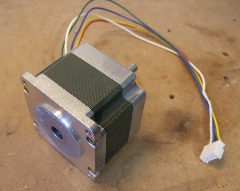
It has a mount for a Nema frame motor. I have a few of these lying around but unfortunately the shaft exits from the wrong end so I will have to mount one on pillars.
These are 1.8 degree step motors so with half stepping I will get 400 steps per rev. Each rev of the leadscrew moves the carriage 20 mm so I will get a resolution of 0.05 mm. It doesn't need to move very fast so I will try to get away with a simple constant voltage unipolar drive circuit.
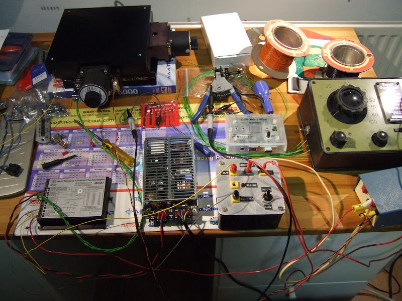
The RepRap machine uses a network of Microchip PICs plus a comms board to control the axes and the extruder(s). The controller boards are multi-purpose so this gives a flexible scheme for experimenting and extending the machine. This topology does not make so much sense for HydraRaptor because I have invested in a set of professional quality axes which I hope to be using in a stable configuration for a long time. Using three controller boards plus a comms board to drive these is a bit over the top.
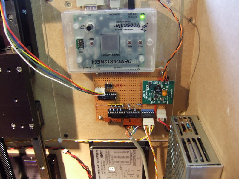
Instead I have chosen to use a demo board that I had lying around to control all three axes. This is a DEMO9S12NE64 from Freescale Semiconductor. It has an on-chip Ethernet controller and a good array of analog and digital I/O ports plus serial ports, timers, etc. It comes with a free TCP/IP stack and a CodeWarrior IDE, C compiler and debugger.
I bought this a couple of years ago from Digikey to acquaint myself with Ethernet and TCP/IP but had not really done anything with it. Strangely, although the chip has masses of I/O, only a subset of this is available at the connector and some of these lines are also connected to the on-board switches and LEDs. Annoyingly the C compiler has a 12K code limit but that should not be a problem for this project. The IDE and debugger are not the best I have used and I have seen the compiler produce some terrible code. There is no excuse for this as the instruction set of the 9S12 is fully featured and well suited to C, unlike say the PICs. Sadly most C compilers I see these days produce worse code than one I used 20 years ago.
It comes with a preloaded monitor program which allows code to be loaded into on-chip flash via a serial port and then debugged at the source or register level with breakpoints and single stepping, etc. All in all the dev kit is not too bad, certainly nicer than the Microchip stuff.
I will use Ethernet to link my machine to the PC as that gives me complete freedom where I locate it. There is enough I/O to drive an extruder as well as the axes. I may well do that initially, but eventually I will use one of its serial ports to drive a network of head controllers.
One snag of using the demo board is that it is 3.3V volt logic. My XY table uses 5V logic so I had to do some level translation and that is most of what the veroboard underneath is about. The outgoing signals to the opto inputs of the stepper controllers are driven by a 7407 open collector buffer. The proper way to handle the incoming signals would be to use a level translating buffer chip but I didn't have any to hand and I suspect they are not available in leaded packages as most 3.3V stuff is surface mount. Instead I buffered them with a 74LS244 and then used potential dividers to drop the voltage. If I had not buffered first I would have reduced the noise immunity in the long leads around the machine which would not be good. This way it is only the noise immunity across the board that is slightly compromised.
Other things on the board are the z-axis driver and a 2A switching regulator which steps down the 24V to 5V to drive the level changing logic. This is actually an L5973 evaluation board from ST. Doing this with a linear reg would waste a lot of power and need a big heat sink. The DEMO9S12NE64 comes with its own 6V mains PSU but I found it works fine fed from 5V as well.
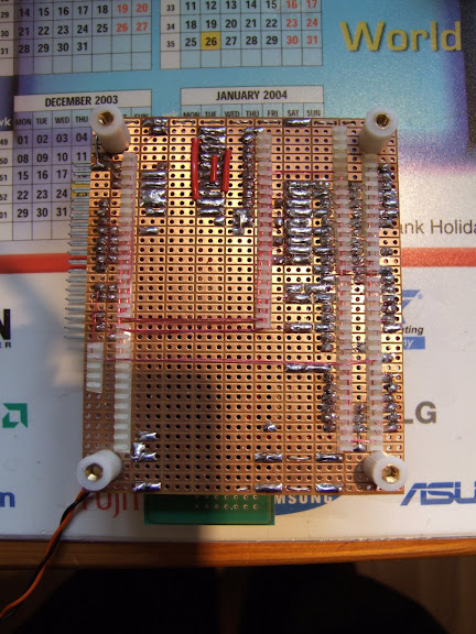
This is quite a quick way to produce high density prototype boards but it is a bit fiddly and requires a lot of concentration. It is not easy to make changes afterwards either.
In summary I was able to cobble together the control system from bits I already had.
I came across this object designed by Gorg Huff in the RepRap objects wiki. It was such an interesting organic shape, completely different from anything else I have printed, that I had to try it.
It was a bit too big for my machine so I scaled it down and printed it diagonally.
It took about 4 hours plus an hour for the raft. Because the sides slope in quite quickly, Skeinforge switches to 100% fill for a lot of the layers because the edges don't have anything two layers above them. This can be fixed by selecting 3 extra shells on sparse layers. That means the infill starts far enough from the edge to have something two layers above it. You get a stronger object with less plastic that way.
Having established that I want to move to a stepper driven extruder I set about designing a new extruder controller for HydraRaptor. I fancied using one of the Allegro micro-stepping chopper drivers.
With these chips there are a few things you can adjust by changing component values, like the off time, minimum on time and percentage fast decay. The data sheet explains what they do and gives the formulas but it's not obvious what you should set them to for a particular motor.
Not having any previous experience with Allegro drivers I decided I needed to knock up an evaluation circuit. Fortuitously Zach had sent me some PCBs a long time ago that were his first version of the Stepper Motor Driver v2.0. They used the PLCC version of the A3977.
PLCC packages were a bit of a halfway house between through hole and surface mount. They have leads which come out of the side and then curl underneath.
They are handy for programmable devices because you can either surface mount them or put them in sockets (which can be either SMT or through hole). The problem with them in this application is that using a socket is not recommended for current and heat dissipation reasons.
That makes the package a worst of both worlds solution. It is big and bulky like through hole parts but still difficult to hand solder because the pins are underneath. The surface mount version of the A3977 is a fine pitch (0.65mm) TSSOP with a heat slug underneath, so again not easy to solder by hand, it really needs to be done by the solder paste and oven / hotplate method.
Zach moved to the A3982 on subsequent versions, which is easy to hand solder because it is in a SOIC package with 1.27mm pitch. It also has a lower external component count. The down side is that it does not do micro stepping and is only 2A rather than 2.5A. I will probably use the A3983 (which is like the A3982 plus micro stepping and in a TSSOP package).
I managed to hand solder the PLCC at my second attempt. My first attempt had a short, which damaged the chip. I damaged the board removing it (with a cutting disk), so I had to start again on a second PCB. Lots of cursing! The lesson is always to meter a PLCC for sorts before powering up as you can't see shorts underneath it.
Here is my test lash up: -
I can set the step rate with a signal generator, vary the supply voltage from 8 to 35V, see the temperature of the chip and look at the current waveform on a scope .
The initial results were disappointing due to a couple of problems: -
The first was that the chopping occasionally had glitches in it. With the motor stationary I could hear it clicking, and with a scope I could see some cycles shorter than they should be. It got worse with higher supply voltages. At low speeds it did not make much difference, but it did lower the maximum speed. I tracked it down to a lack of high frequency decoupling on the 12V rail. I added a 220nF de-coupler close to the chip and the problem went away. Adding it further from the chip actually made it worse.
The next problem was that the microstepping was very uneven. I had noticed that same effect with the z-axis of my Darwin using the $800 microstepping drivers (that I got cheap) that I use on HydraRaptor. At the time I put it down to the small, large step angle tin can motors I was using at the time not being very linear. When I moved to larger 7.5° tin can motors I still had the same problem, and even with the Keling NEMA23 1.8° motors it did not seem right. This puzzled me because they are very similar to the NEMA23 motors on HydraRaptor, which work well with the same drivers. The shaft encoders have the same resolution as the ×10 microstepping and they are always spot on or one count out, so pretty linear.
With the A3977 it is easy to get an idea of the current waveform of the motor by measuring the voltage on the sense resistors. It should be a stepped sine wave like this: -
Regardless of which way the coil is energised, the current flows to ground through the sense resistor, so the waveform looks like a full wave rectified sine wave. The current only flows in the sense resistor when the chopper is in the on state though. In the off state the current is circulating through the coil and the bottom two transistors of the H-bridge, so the current in the resistor is zero. That is why there is a bright line along the X-axis. On the falling edge of the wave you can see the sense current goes negative. That is because the chip switches to fast decay mode. When the chopper is in the off state, instead of short circuiting the coil, it reverses the voltage on it, causing the current to flow backwards through the sense resistor onto the supply rail. It only spends part of the switching cycle in fast decay so you see positive current, a lot of zero and some negative current, hence the relative brightness of the lines. This is a case where an analogue scope gives you more information than a digital one.
Initially the waveform looked like this, it was somewhat distorted: -
The current rises too quickly at the start of the waveform. The chopper has a constant off time (20uS in this case) and varies the current by changing the on time simply by turning it on until it reaches the target value. But, there is a minimum on time of about 1.4uS, called the blanking period. During that time it ignores the current sense signal to avoid false readings due to ringing on the switching waveform. That means there is a minimum mark space ratio of 1.4 : 21.4 in this case. That sets a minimum current, which also depends on the ratio of the supply voltage to the motor voltage. If this minimum current is more than the lowest microstep value (19.5% of the peak for 1/8 steps) then you get a distorted waveform as above, and the steps are uneven.
To fix it you can lower the supply voltage, raise the current setting or increase the off time. The latter reduces the chopping frequency. If it is below about 15 kHz it will be audible when the motor is stationary. It can also start to beat with the stepping frequency when running at high speeds, particularly when micro stepping, as the step rate is n times faster.
This form of distortion is analogous to crossover distortion on a class B audio amp. You can also get the equivalent of clipping if you use a high voltage motor on a low supply voltage. If the current setting is set to a value which is more than the motor will draw when connected to the supply, then the top of the waveform is flattened off and again the microsteps will be uneven.
Yet another form of distortion occurs when running at high speed: -
Here the back EMF from the motor acting as a generator is preventing the current from falling fast enough to follow the sine wave. This can be fixed by increasing the Percentage of Fast Decay, set by the voltage on the PFD pin. If there is too much you get excessive ripple as shown here: -
For a particular speed and motor there is a sweet spot which sounds audibly quieter: -
So setting up a microstepping drive is not straight forward unless you have an oscilloscope. You can tune the PFD by ear though, as this video demonstrates: -
You can also see the other forms of distortion if you attach a long pointer and step it round slowly.
Another lesson is that you cannot simply just set the current to accommodate different types of motor. You really need to be able change the off time and the PFD as well, especially if you use different supply voltages.
So I solved the mystery of why microstepping does not work well with the expensive drives on my Darwin. They are rated at 7A but I am only using them at 1A, I am also using low voltage motors on a 36V supply. I bet it is a constant off time chopper and the minimum current is too high.
My wife has been asking me to make something to prop up the overladen branches of our dwarf apple tree for a few weeks now. I put it off while I was set up for ABS because I knew I did not have enough to finish my Darwin. Now that I have switched the machine to HDPE it is no problem, but it is now a few days late as one large branch has already snapped off!
We have lots of plastic covered metal poles so all I needed to do was make some Y-shaped end pieces. My first attempt went a bit chaotic while making the arms: -
I wasn't watching it but I figured it got too hot when doing the small pieces so I made the arms thicker.
Better but still very rough, it should look like this :-
I cleaned it up with a penknife and it was functional but it felt more whittled than extruded.
I made a couple more with even thicker arms but I was around to observe what was going wrong this time: -
When building the curved arms Enrique's software switches to 100% fill because it decides part of the layer is two layers from an outer horizontal surface, which a thin sliver down each side is. That would not be a problem in itself but because I have the infill overlap option set it ends up with slightly too much plastic on the 100% layers. As the height increases this excess builds up until the nozzle is actually submerged in the object while it is building it. Amazing that it manages to make anything resembling the correct shape!
What really needs to happen is that if the infill overlap parameter is set then the head needs to lay down the infill slightly faster so that the amount of plastic is still correct. I ran into the same problem with ABS when making an object with 100% fill.
I made a fourth version with the infill overlap set to zero and it was a lot better: -
Still very blobby but all the blobs are down to extruder overrun and easier to carve off. Overrun is worse with HDPE because it seems to be a more non Newtonian liquid than ABS. I.e. it compresses and expands more than ABS does, so when the extruder stops it oozes for longer.
I haven't tried anything to stop ooze yet. Simply stopping the extruder before the end of the line like the RepRap host does should improve it and is easy to do. Reversing the motor drive should also help. Simply stopping causes the extruder flow rate to fall exponentially but backing up a little should stop it completely in a finite time. The shaft encoder can then be used to go back at full speed to where it was before it backed up. There will still be some ooze without a valve but I think it could be a lot better.
Here is the final version cleaned up: -
And here is the tree with four crutches installed although only three are visible from this view though: -
Last year I bought a Mooshimeter wireless 2-channel multimeter. It is a multimeter front end that links to your mobile phone with Bluetooth and displays the results in an app.
It is handy because you can read it remotely, it can measure voltage and current simultaneously and display power, it can log to an SD card and graph the results. It can also speak the results.
Despite all these good features my "go to" multimeter is still my EEVBlog branded Brymen BM235. So my Mooshimeter sits in a drawer for most of its life. When I get it out it usually wants to do a firmware update, which needs fresh batteries. Because it has no off switch the best you can do is put it into shipping mode. It still flashes its LED occasionally, so the batteries run down over a period of several months and are then not up to doing a firmware update.
Devices with no proper off switch are a pain if you only use them rarely because the batteries are always flat when you come to use them. This is particularly a problem because modern Duracell batteries seem to leak and corrode as soon as they are flat. This didn't used to be the case. I found some very old ones that I had abandoned in outdoor devices that I expected to be corroded to hell but in fact they were not corroded at all, despite being well past their use by date. In contrast I have had many corrode recently that were flat, but still well within their use by date. I have stopped buying Duracell and now use Costco's own Kirkland branded ones. It is too early to say if they corrode or not.
So I normally remove the batteries from devices I use rarely but with the Mooshimeter this involves removing the casing that is held together by two screws. I decided to add a switch to it but it has a cat III safety rating and cutting a hole in the case would void that.
I had two ideas to get around this: the first was to put a normally closed reed switch in series with the batteries and 3D print a cradle with a magnet in it to turn it off. My second idea was to use a mercury tilt switch to turn it off when placed upside down. I ordered both but as the mercury switches arrived first I implemented that and it works well.
I decided the easiest point to break the battery circuit was the link between the two cells. For some odd reason that is a copper fill rather than just a track. It is on the top side of the PCB so I had to desolder one of the contacts to get at it. Fortunately the battery contacts have thermal relief connections so I just cut two of those to isolate the pad.
I then made an insulating washer out of Kapton film. I used that because it is very thin and can handle soldering temperatures. I stamped it out with a hole punch but I found it very difficult to get the hole concentric. This is my third attempt that was just good enough:
And here it is in place:
I reinserted the clip over the top and resoldered it. I then soldered the tilt switch between the two now isolated battery terminals.
When upright the contacts are bridged by the mercury, which is very low resistance. When I turn it upside down the mercury flows to the top of the bulb and isolates the batteries.
So all I have to do is remember to place it upside down in its case. If you want to attach the meter to something moving then the reed switch idea is the one to go for. I think it can probably be mounted in the same place if you use a neodymium magnet. You can get it nearer the back of the case by mounting it on the other side of the PCB but I don't know if that affects clearance distances for class III.
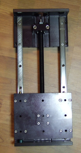
The XY stage turned out to be a really nice piece of kit. It is an XYR-8080 from NEAT, details here. It also came complete with a pair of MDM7 stepper motor drivers. These are bipolar, constant current, micro-stepping with anti-resonant circuitry and opto isolated inputs, i.e. top of the range. Perhaps I should explain each of these terms :-
Bipolar versus Unipolar drive
Stepper motors usually contain two electromagnets which need to be energised in one of two magnetic polarities, giving four combinations or phases. If this is done with a single coil per electromagnet then the electronics must be able to drive a positive or negative current into each coil. This is bipolar drive and requires four transistors per coil, i.e. eight per motor. Alternatively the coils can be centre tapped which effectively creates two coils per electromagnet wound in opposite directions. One of these can be energised at a time to produce opposite magnetic fields. This only requires one transistor per half coil, i.e. four per motor. The advantage of unipolar is that the electronics are cheaper but as only half of the windings are energised at one time the amount of torque available from a given size of motor is less.
The field produced by an electromagnet and hence the torque of the motor is proportional to the number of turns times the current. The maximum current that can be applied is limited by the maximum allowable temperature rise. The heat generated in the windings is proportional to current squared times resistance. This means that if a unipolar motor is operated in bipolar mode then the maximum current is root two times less because the resistance of the full winding is double that of the half windings. However, the number of turns is doubled so the torque is root two greater.
Constant current versus constant voltage
The simplest way to drive a stepper is to apply a constant voltage to the coils. The problem with this is that when a voltage is applied to a coil the current builds up gradually at a rate proportional to the voltage divided by the inductance until it reaches the steady state defined by the voltage divided by the resistance. This causes torque to fall off with speed because at higher step rates the current does not get time to reach its full value before the next step.
A better driver system is to apply a much higher voltage to the coil to get the current to rise quickly and then turn it off when it reaches the correct value. The current then starts to fall at which point the voltage is applied again. This on / off switching occurs at a high enough frequency to avoid producing audible noise.
Micro-stepping
This is a technique to increase the number of steps per revolution by varying the current in the two windings in a sinusoidal fashion. In this case it increases the number of steps from 200 to 2000 per rev. As the screw threads have half an inch travel per rev this gives me a step size of a 4000th of an inch or just over 6 micrometers. The target for RepRap V1.0 aka Darwin is 0.1mm resolution so I am well within that that! The only downside is that the maximum travel is only 150mm in each direction compared to Darwin's 300mm.
Another advantage of micro-stepping is that it produces smoother running at low speeds.
Anti-resonance
Because the force applied by the motor increases as it is displaced from its resting position it behaves like a spring. This together with the mass of the rotor and the load forms a resonant system. If the step rate gets close to the resonant frequency oscillations build up and the motor gets out of step and / or stalls. This is a major problem with high speed operation of stepper motors. An anti-resonant drive monitors the drive waveforms to detect when resonance starts to occur and adjusts the drive current to dampen it down. This allows the motor to be stepped through its resonant band to achieve higher speeds. Clever stuff!
Opto isolated inputs
The step and direction inputs are electrically isolated from the drive electronics by opto couplers. This avoids heavy motor currents sharing the same ground path as the logic signals, which can cause signal corruption.
The XY stage also includes hall effect limit switches and 2000 step shaft encoders. A great find, the challenge now is to build a machine that does it justice.
Here it is being put through its paces with a signal generator on one axis.
It can easily handle step rates up 6kHz which is about 40mm per second. With a bit of ramp up and ramp down I think it would go well above 10kHz. Also I have the full windings connected for maximum torque. The motors are centre tapped so I have the option of using half the winding. This gives root two less torque but one quarter of the inductance, so should be better for higher speeds if needed.
I am pleased to say HydraRaptor is now back up and running after my accident where I connected 240V to a 3.3V logic input. I had to replace most of the electronics, which is annoying because I originally made it out of things I already had, so it cost me nothing, but replacement parts cost me around £180 and obtaining them set me back three weeks.
Things that were destroyed:
My ADSL router: a friend kindly gave me a replacement.
My PC's serial port: I replaced it with a USB to serial adapter.
The Freescale DEMO9S12NE64 evaluation board that I used for my axis controller: next day delivery from Farnell.
The EZ430-T2012 eval board that I used for the extruder controller, fortunately the spindle controller was not connected at the time so that survived.
The ULN2803 and 7407 chips on my interface board.
The optical shaft encoder chip on my extruder.
The NEAT MDM7 stepper driver on the X axis. The only thing wrong with it was the direction input was not working. They are opto coupled so it should have been just a simple matter of replacing the opto, but the whole thing is potted in epoxy resin so it is impossible to fix. I managed to find a replacement on the web and I have got some spares on the way as well.
Things that survived:
Both power supplies and all the local voltage regulators.
The Y axis stepper driver.
The X-Y table shaft encoders and Hall effect limit switches.
The protected MOSFETs on the extruder controller.
I spent the time waiting for the stepper controller to arrive from the US improving my firmware. I fixed a long standing issue with timing: I was doing my Ethernet comms under interrupt and the stepper motor timing with a higher priority timer interrupt. Unfortunately, the 9S12 does not have nested interrupts, so the interrupt priority is pretty meaningless. I fixed it by moving my comms to the foreground as the machine has nothing else to do in the foreground but process commands coming from the network so there was no point in doing it with interrupts.
I also added acceleration and deceleration to my stepper driving software. I am aiming to lay down 0.25mm filament at 64mm/s. My XY table can easily move that fast but I didn't like the thump I was getting when it started and stopped. It's a bit much to ask it to accelerate a few kilograms to 64mm/s instantly! The datagram for the goto_xyz command now includes a table of delays to use for the first and last n steps. It remains to be seen how much distortion I will get from not moving at constant velocity. At the very least the acceleration will be useful in speeding up the moves when it is not extruding.
Another ancient piece of equipment I have is this Telequipment D32 mains / battery operated portable oscilloscope.
Telequipment is an old brand name used by Tektronix in Europe. I think it was made in about 1972 for servicing TVs. I bought it in a broken state from a friend of a friend in the mid 1980s. The six NiCad D cells had gone short circuit and the mains transformer was burnt out. I replaced both of those and as far as I can remember that was all I had to do to get it working.
I did get a lot of use from it as for many years it was the only working scope I had. I haven't used it much in recent years though because I now have several much better scopes. It is the only battery powered one I have, although I do have two USB digital scopes which are battery powered if I run them from a laptop.
I powered it up fully expecting the NiCads to have died again, but amazingly they still work to some extent. The only thing wrong with it was the trace was slanted and the trace rotation control didn't have enough range to correct it fully. It seemed to max out in one direction and then have a large dead band.
I did a bit of research and managed to find the schematic. I must admit that somehow the fact that a beam rotation circuit is needed because of the earth's magnetic field had completely passed me by, or else I once knew and have since forgotten. This is despite building my own scope with valves (vacuum tubes) when I was 13 and using CRT scopes for many years after.
The rotation circuit is below. After looking at it and making some measurements I was surprised to find it to be a design fault rather than a faulty component.
The base of TR301 can be varied between ±7.5V with R303, so one would expect the emitter follower to drive the coil over that range with a VBE offset. The problem is the coil has a resistance of about 1kΩ, so the pull down resistor R314 can't drag it below -3.5V. This means the control has no effect for a significant part of its travel and the range of the correction is asymmetrical.
To fix the problem I removed R314 and replaced it with a PNP emitter follower. That gives push-pull symmetrical drive between about -6.8V and 6.8V. The only dead band is a small one around 0 due to the VBE drops (classic crossover distortion). It also has the advantage of not wasting the current through R314, all the current now flows through the coil.
This is a view of the board before the mod. It is ancient technology, all discrete transistors and hand routed PCBs, including vias made with what looks like soldered in brass rivets.
I don't know why all the transistors are socketed. The only other time I have seen that was in a Russian transistor radio, but they were germanium PNP transistors, so may have been unreliable. These are silicon planar epitaxial so should be reliable and never need replacing. Perhaps they did it because they thought soldering would damage them. Or perhaps they were just old school designers used to valves.
Anyway the scope is a joy to work on because all the PCBs hinge out to allow access to both sides with the scope still operational. See www.youtube.com/watch?v=BOeEbyIllcM for a look inside a D32.
Here is a view of my modification: -
I replaced R314 with a 2N4403 (any PNP transistor should work) and linked the base to a handy via. Don't worry about the proximity to the ceramic capacitor's lead, it is the same net.
So a simple mod but I don't understand why I need it now. Perhaps the earth's magnetic field has changed since I last used it. It was about a decade ago!
Update
The scope has always had a delay between switching on and starting up. The power LED comes on about a second after it is switched on. This got longer and longer and then it stopped starting reliably at all. I had always assumed the delay was caused by a capacitor charging in a bias circuit for the inverter but on examination of the schematic I fount that wasn't possible because all the capacitors have a low impedance supply.
It turned out the be the on off switch. I measured about 3V across it in the on state. The contact resistance measured 0.3Ω but that should only drop 0.3V at 1A, so it seems to be a strange non-linear resistance and it must get lower over time as it heats up.
The switch is part of the brightness potentiometer and it is operated by pulling the knob out and pushing it in. Normally potentiometers with switches operate it at the start of the rotation but this allows the brightness setting to be retained. It is also a small form factor so I didn't think I would be able to find a replacement. As it is riveted together I didn't think I would be able to repair it or even get any switch cleaner into it.
It is actually a two pole switch, the second pole is used to change the charge current of the battery to include the scope current when on. I figured 0.3Ω would not affect that circuit as it has 150Ω in series, so I swapped the connections over. It now starts instantly although it does take time for the tube to warm up of course.
I aimed to build my Mendel in time to show it at the Makerfaire in Newcastle but completely failed. I had two weeks to build it, which I thought was plenty. In actual fact it took closer to three weeks before I got it printing successfully. I had no major problems, just a few snags here and there and a severe underestimation of how long it would take on my part.
Printed Parts
Unlike when I printed two sets of Darwin parts, printing the parts was the easy bit. This was due to three breakthroughs I had at the beginning of the year: -
The heated Kapton bed removed the need for rafts, which not only take a significant time to print, but also can take a lot of manual work to remove.
The extruder fast reverse got rid of all the strings, which also took a long time to clean up, especially from inside the Darwin corner blocks.
The "no compromise" extruder is so reliable that I have the confidence to do multi-part, layer by layer builds, which gets a lot more on the table, allowing longer unattended operation.
I printed the parts with 0.4mm or 0.375mm filament and with 25% infill. For the larger parts I used two outlines for strength. Since the large parts don't need fine detail, I think printing them with 0.5mm filament and one outline would be quicker, but that would need a bigger nozzle.
The weight of the parts, not including the extruder, was only 730g. I printed the outlines at 16mm/s and the infill at 32mm/s, so it's hard to say the total time. Assuming an average speed of 24mm/s at 0.4mm diameter gives about 3 mm3/s. That would put the total time at about 65 hours. I did it as a background task over a few weeks. A lot of the parts were printed as experiments with heated beds.
Rods
I took me an evening to cut all the rods. The method I used was to nail a stop to my workbench to line up the rod against a metre rule.
I then lined a piece of masking tape up with the correct measurement and wrapped it round the rod to mark the place to cut. I also wrote the name of the rod on the tape to make it easy to identify later.
A Black & Decker workmate makes an ideal vice to hold the rods while sawing. I rotate the studding until the thread lines up with the edge of the masking tape. That guides the saw to start in exactly the right place.
I used BZP for all the studding except the z-leadscrews, for which I used A2 stainless steel because it is smoother and generally straighter. I bought the rods from Farnell and even the BZP studding was very straight, a lot better than the stuff you get in B&Q. I also used A2 for all the bars.
It was very hard work sawing the A2 until I switched to a new blade and used Trefolex cutting compound. I am not sure which made the most difference, but I could then cut the A2 much easier than I had been previously cutting the BZP. I wish I had done that earlier, it would have saved a few hours.
Thick Sheets
The thick sheet parts are not really suitable for making by hand, particularly the squashed frog. They have lots of slots, which are hard to make without a milling machine or a laser cutter, etc.
I am not sure exactly what the hole in the bed and the purge plate are for, so I made the bed a simple rectangle with four holes. I am using my own electronics, so I made the two circuit board plates to suite. I simply cut rectangles and I marked the holes and drilled them in the right place, so no need for slots. That just left the squashed frog.
I made a much simpler design with drill centres on it. There is no need for the bulging legs and sloping shoulders. I think they must be just to make it look more like a frog. Fine if you you are CNCing it, but a PITA if you have to make it by hand. Also the holes for the opto tab and the purge plate are mirrored for no apparent reason, so I made it chiral.
This just starts as a rectangle with some holes in it. Then the large slots are made with a saw thin enough to turn in the holes. The outer holes that mount the bearings can be round because they are in a a fixed place, dictated by the holes in the bed. The inner holes need to be slots because the bearings are adjustable. I just left them off the template and marked them with the bearings adjusted and in place.
I made the sheets from 3mm Dibond, which is below the recommended thickness, but seems stiff enough. It is also light weight and very easy to machine.
Thin Sheet
I didn't have any optos, so I used micro switches for my end stops, hence didn't need any thin sheet parts. I simply attached them to the bars of each axis with P-clips. A little RepRapped bracket would be better but I was building this in a hurry, so had gone into bodging mode at this point!
They seem to have sufficient repeatability and certainly will when I replace the electronics with my new design, which will know the motor phase, reducing the uncertainty by a factor of 32. It is the same switch that I have used on the z-axis of HydraRaptor, which has proven totally reliable. They seem to be this one from RS, not cheap.
Belts
These were easy enough to split but, because the reinforcing wires run in a spiral, the blade tends to follow one for a while before managing to cut through it. That leaves a ragged edge with a bit of wire sticking out.
I didn't understand the rationale for slackening the belts until you just don't see backlash when moving one motor detent. I am microstepping anyway, so a motor detent is not significant. I made my belts good and tight.
Snags
I had a few snags with the mechanical assembly: -
The x-axis spacers are too short. The STL files are 5mm shorter than the parts in the STEP assembly. That caused the motor to clash with the nuts on the 360 bearing.
The 180 bearing at the other end was about 10mm from where it should be.
A simple fix was to slide the axis along leaving a 10mm gap to the spacer, the only problem remaining is that the spacers rattle at certain step rates.
The STEP model shows this gap should be only 5mm, but I have been unable to find the discrepancy. My rods and inspection distances are correct and the ends of the rods are flush with the clamps, as they are in the model.
The bed springs seemed to be too long to compress to the length of the bed-height-spacer-31mm_1off, which is not actually 31mm, but 29mm, so I don't know what gives there, I just spaced them a bit higher.
The bolts in the z-bar clamps are too long to allow the bearing to be inserted. I replaced them with shorter ones.
Similarly the bolts in the x-carriage get in the way of the extruder I fitted.
The J3 jigged distance did not seem correct. The distance between the y-bars is set by the J2 distance and the 3 nut spacers.
The gears work well, with very little backlash, but the small one has some movement on the motor shaft. It is just a press fit with a flat on the shaft. I need to redesign it with a captive nut and grub screw.
I didn't have a suitable M8 shoulder bolt so I made one from brass by attaching a nut with a pin through it.
I hobbed it with an M3.5 tap. I haven't measured the grip, but I get the impression it is not as high as Wade gets, I am not sure why.
For the bottom half of the extruder I used some parts that Brian was looking for volunteers to test for him.
The insulator is made from PEEK with a PTFE liner. The idea being to get the strength of the PEEK and the slipperiness of the PTFE. It seems to work well with PLA, which is all I have run through it so far.
The barrel is long because it is designed to take nichrome, but I just screwed it into a block of aluminium with a vitreous enamel resistor in it.
This was left over from a previous experiment. I have now moved onto a smaller resistor size, so this block could be smaller. The barrel could be a lot shorter with this arrangement and that would give less ooze and less viscous resistance.
The extruder works well with PLA. The main problem with it is that it mounts at right angles to the x-axis, so the motor severely restricts the maximum height of the z-axis. Another issue is that to remove it you have to remove the motor to get at the bolts. To remove the motor you have to remove the big pulley to get at the motor's bolts, to do that you have to remove the pinch wheel assembly. I.e. to remove the extruder you have to completely disassemble it!
Electronics
To get up and running quickly I used the same electronics that I use on HydraRaptor. The only difference being that I used MakerBot V3 stepper drivers. These use the A3977 chip and give x8 microstepping. That gives an axis resolution of 0.025mm, but more importantly gives nice smooth running.
When the weather was exceptionally dry I found they are very sensitive to static. A discharge to any part of the machine would cause the A3977 to shut down its outputs and draw enough current from the 5V rail to cause the 100mA regulator to current limit. The red LED on the power rail goes dim. Powering off and on again fixes it and there doesn't seem to be lasting damage. I suspect that might not be the case if the 5V rail was not current limited. Apparently the only way to fix it is to add external Schottky diodes. That is very disappointing as one of the nice features of the chip is that it is supposed not to need them. I will investigate further to see if all eight diodes are needed before making my own board.
Firmware
I used the same firmware as HydraRaptor. I just added some compile time conditionals to cope with two pin outs and a different IP and MAC address for each machine. I also had to change from 16bit to 32 bit positional commands because the axes are bigger.
Software
I used the same Python software as HydraRaptor but I had to re-factor it quite a lot to support both machines. I added a class to represent the Cartesian bot which holds the axis resolution, direction, maximum speed and acceleration plus the IP address. I also added a class to represent the extruder controller as I have calibration values unique to each board. I already had classes to represent thermistors and extruders.
I can run both machines at the same time from one PC and, because I only use the Skeinforge output for the toolpath, I can use the same sliced files for either machine. This is despite the fact that they run at different speeds and are loaded with different plastic.
Results
So here is the finished machine: -
And here is a video showing it being tested: -
I am running the X & Y motors at about 0.75A and Z at about 1A. I have set the maximum XY speed to 100mm/s, but I think it could go a lot faster. Z only goes at about 5mm/s because not only is it a threaded rod drive, but it is geared down by the belt and pulleys!
I haven't printed a lot yet, but so far the results look as good as they do from HydraRaptor. The next thing to do is add a heated bed and try ABS.