Showing posts sorted by date for query switches. Sort by relevance Show all posts

Sunday 13 December 2009

Motoring on with the A3977

Previously I have blogged about how to set up the Allegro A3977 driver chip to suit a particular motor: -

hydraraptor.blogspot.com/2009/07/lessons-from-a3977
hydraraptor.blogspot.com/2009/08/motor-math
hydraraptor.blogspot.com/2009/08/mixed-decay-mixed-blessing

Most boards I have seen using the A3977 and similar chips just have a current adjustment, with all the other values fixed. Unless you strike lucky this is not going to allow accurate microstepping because the off time and PFD need to be adjusted to suit the motor and supply voltage.

A while ago Zach sent me samples of the prototype V3 stepper controller kits and the NEMA17 motors used on the MakerBot. I made up the board using my SMT oven (pizza oven controlled by HydraRaptor, more on that later).


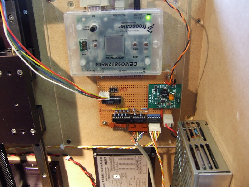
It works well, but the initial component values are not optimum for the motor, so I decided to make a test bench from the older prototype board that I have been experimenting with. I RepRapped a chassis for it with a panel to mount some switches to vary the timing components.


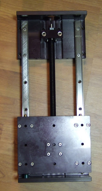
The chassis is one of the biggest parts I have made, not in volume, but in overall expanse. It warped a little, despite being PLA, heated bed coming soon!


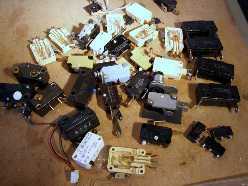
The switch on the left must be at least 20 years old and the one on the right more than 40 but they both still work fine. I save all this junk and eventually it comes in handy.

I also have potentiometers on V
ref and PFD, so together with a bench PSU and a signal generator I can vary every parameter.

I knocked up a label on a 2D printer, it's so much easier to make this sort of thing than it was when the switches were born!


Zach has updated the board to have four preset potentiometers to make it fully adjustable. There are test points to allow the pots to be set to prescribed values with a multi-meter.

Vref and PFD can be measured as a voltage, but the two RT values have to be set by measuring resistance with the power off. My multimeter seems to give accurate readings of these despite them being in circuit. A good tip is to measure the resistance with both polarities and if it reads the same either way round then it is most likely the chip is not affecting the reading.


So here is a list of motors and optimised settings: -

MakerBot Kysan SKU1123029 NEMA17


This is the motor that MakerBot use for the axis drive on the Cupcake, details here. It is actually a 14V motor, so is not ideally suited to being driven from a 12V chopper drive. You normally want the motor voltage to be substantially lower than the supply.

You can't run it at its full current because the duty cycle would tend to 100%. With a fixed off-time, the on-time tends towards infinity and the frequency drops into the audio range.
In practice I found the maximum current at 12V was 0.3A, any higher and the microstepping waveform was distorted on the leading edge due to the current not being able to rise fast enough.


To maintain the sinusoidal waveform at faster step rates requires the current to be lowered further, 0.25A gives a good compromise. It is not a bad idea to under run steppers anyway, otherwise they can get too hot for contact with plastic.

I used the minimum values for CT and RT, i.e. 470pF and 12K to keep the chopping frequency as high as possible, so that it is outside of the audio range. Not only is this a good idea to keep it quiet when idling, but also you want it much higher than your stepping frequency, otherwise they beat with each other.

The values give a minimum frequency of ~17kHz @ 0.3A and a maximum of ~150kHz on the lowest microstep value.
17kHz is not audible to me, but younger people might be able to hear it. There is still some audible noise at the point in the cycle when both coils have similar currents and so similar high frequencies. The beat frequency, which is the difference of the two, is then in the audio range. It isn't anywhere near as loud as when the chopping is in the audio range though.

I can't see any spec for the maximum switching frequency although a couple of parameters are given at less than 50kHz. I suspect 150kHz is a bit on the high side, which would increase switching losses, but with such a low current compared to the rating of the chip I don't think it is a problem.

One problem I had initially was that the switching waveform was unstable. It had cycles with a shorter on-time than required, which let the current fall until it then did a long cycle to catch up. The long cycle gave a low frequency that was back in the audio range.


I think it was a consequence of the motor needing a very short off-time in order to be able to have the duty cycle nearly 100%. The current hardly falls during the off period, so a little noise due to ringing can trigger it to turn off too early. It is not helped by using the minimum blank time. I fixed it by putting 1uF capacitors across the sense resistors.

The PFD value is best set to 100% fast decay with this motor.

It works better with a 24V supply. The full 0.4A current can be achieved (but it gets much hotter of course) and it maintains microstepping accuracy at higher step rates than it does on 12V.

MakerBot Lin SKU4118S-62-07 NEMA17


This is the NEMA17 that MakerBot used to supply. It is at the opposite extreme compared to the one above, i.e. it is a very low voltage motor, only 2V @ 2.5A. As mentioned before, this causes a couple of issues: -
  1. The inductance is so low that the ripple current is significant compared to the lowest current microstep, causing positional errors. OK at 2A, but gets worse with lower currents.
  2. It is difficult to get 2.5A from the A3977 without it overheating. The PCB layout has to be very good. The datasheet recommends 2oz copper and four layers. 2A is no problem and that is the maximum with the 0.25Ω sense resistors fitted to the board.
At 2A the motor runs at about 40°C, so just about OK for use with PLA. The chip gets a lot hotter, about 77°C measured on the ground pins.

I used a value of 56K for RT and 2.1V on PFD. To some extent the optimum PFD value depends on how fast you want it to go.

Motion Control FL42STH47-1684A-01 NEMA17


This is the recommended motor for the Mendel extruder, details here. After buying a couple of these a friend pointed out that Zapp Automation do the same motor with dual shafts for about half the price!

This is a high torque motor so it is longer and heavier than the previous two NEMA17s. Electrically it is in the sweet spot for the A3977 with a 12V supply. The A3977 can easily provide the full current and the switching frequency doesn't have wild fluctuations or drop into the audio range.

When microstepped at 1.7A it gets to about 43°C but the chip only gets to 56°C.

I used 39K for RT and 0V on PFD, i.e. 100% fast decay.

I have high hopes for this motor as a replacement for the one above that is in my extruder currently. It should give me almost twice the torque and has the correct sized shaft, i.e. 5mm. The Lin and Kysan motors both have imperial shaft sizes which caught me out as I drilled the worm gear for 5mm thinking NEMA17 specified that, but it must just be the frame dimensions.

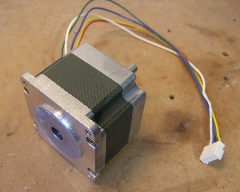
MakerBot Keling KL23H251-24-8B NEMA23


This is the motor I used on my Darwin. It has 8 wires so it can be connected in bipolar serial or parallel. Series has the advantage that the full torque can be achieved with 1.7A which is easily within the range of the A3977. Parallel has one quarter of the inductance so torque will fall off with speed four times slower. To get full torque 3.4A is needed but I found 1A was enough for the X and Y axes. I think Z needs more torque but my z-axis uses different motors so I don't know how much.

An RT value of 56K is fine for currents in the range 1-2A. PFD is best at 0v, i.e. 100% fast decay.

Summary

Here is a summary of the motor specifications :-

Motor Resistance Max Current Voltage Max Power Holding Torque Inductance
LIN 4118S-62-07 0.8 Ohm 2.5 A 2.0 V 10.0 W 0.30 Nm
Kysan SKU 1123029 35.0 Ohm 0.4 A 14.0 V 11.2 W 0.26 Nm 44.0 mH
Motion Control FL42STH47-1684A-01 1.7 Ohm 1.7 A 2.8 V 9.5 W 0.43 Nm 2.8 mH
Keling KL23H251-24-8B Series 3.6 Ohm 1.7 A 6.1 V 20.8 W 1.10 Nm 13.2 mH
MakerBot Keling KL23H251-24-8B Parallel 0.9 Ohm 3.4 A 3.1 V 20.8 W 1.10 Nm 3.3 mH

Here are my suggested settings :-

Motor Current Vref CT RT PFD
Kysan SKU 1123029 0.25 – 0.3A 0.5 – 0.6V 470pF 12K 0
LIN 4118S-62-07 1 – 2A 2 – 4V 470pF 56K 2.1V
Motion Control FL42STH47-1684A-01 1 – 1.7A 2 – 3.4V 470pF 39K 0
Keling KL23H251-24-8B Parallel 1 – 2A 2 – 4V 470pF 56K 0

Sunday 9 August 2009

Mixed decay, mixed blessing

Having set the correct off time to suit my motor I can now micro step it with equal spaced steps, but only if I disable the mixed decay mode.


When the chopper switches off it can do it two ways. It can turn on both low side transistors. That short circuits the motor and lets the current recirculate. If the coil was a perfect inductor and the transistors perfect switches, the current would circulate forever and you would have a superconducting magnet. Real coils and transistors have some resistance, which causes the current to decay, but as these are relatively small the mode is called slow decay.

This is fine and efficient until you take the motor's back emf into account. During the rising part of the sine wave the magnet is moving towards the pole piece, so it generates a voltage that causes the current to fall faster. The on time gets longer to compensate and all is well.

On the trailing edge of the sine curve the magnet has gone past the pole piece and generates a voltage that increases the current in the coil. If it is going fast enough it can mean that the current doesn't fall at all during the slow decay period. As I showed previously that can cause a severely distorted waveform which makes the motor noisy.


The Allegro chips offer a mixed decay mode, where they switch to fast decay for part of the chopping cycle on the downward half of the sine curve. In fast decay mode one low side and one high side transistor turn on and reverse the voltage across the motor. That overcomes the BEMF and causes the current to fall much faster. It also returns current to the supply rail, which can upset some power supplies if there isn't some other load to absorb it.

Mixed decay gives a current waveform like this: -


The off time is fixed, so the current falls further making the ripple greater. If you set the percentage fast decay to give a clean waveform at your top speed, then the ripple increases at slower speeds. It is maximum when stationary, when there is no BEMF and fast decay is not required at all.

The problem is that the target current is the trip point of the comparator, so it is the peak of the chopping waveform. That means the average current is less by half the ripple current giving a positional error.

With the low inductance motor I am using, the ripple current has a large amplitude, so the error introduced when the motor is stationary is about the same as a micro step. That means the first step with fast decay is about twice as big as it should be and the last step is virtually zero.

With the A3977 I can disable fast decay and the steps are fairly even, but fast running is then distorted. The PFD setting needs to change with speed.

With the A3983 that I have used on my new extruder controller the PFD setting is fixed at 31.25%. That means I can't get evenly spaced microsteps with the NEMA17's that I have, when running slowly. Not a big problem with the extruder because I plan to gear it down 40:1, which means one micro step is only about 0.02mm. I am only using microstepping to give smooth motion rather than extra resolution.

The problem is exaggerated because not only am I using a low inductance motor, but I am also trying to run it at 1A, whereas it is rated for 2.5A. At 2.5A the off time would be about 2.5 times smaller, so the ripple would be 2.5 times less. The steps in the current waveform would be 2.5 times bigger, so the distortion would be reduced by 6.25 times. As it is about one microstep now, it would reduce to 1/6th of a microstep, so would be acceptable. The temperature rise would then be 6.25 times greater of course.

I was planning to use A3977s for my axis control though, where positional accuracy is important. I am beginning to think I will be better off just using dual H-bridges and doing the rest in software using a powerful micro with a fast ADC.

To be able to cope with a wide variety of motors you need to change the current, the off time setting and the percentage of fast decay. You also need to take the ripple current amplitude into account to control the average current, rather than the peak. All these things could be automated with a software solution.

Thursday 30 July 2009

Lessons from the A3977

Having established that I want to move to a stepper driven extruder I set about designing a new extruder controller for HydraRaptor. I fancied using one of the Allegro micro-stepping chopper drivers.

With these chips there are a few things you can adjust by changing component values, like the off time, minimum on time and percentage fast decay. The data sheet explains what they do and gives the formulas but it's not obvious what you should set them to for a particular motor.

Not having any previous experience with Allegro drivers I decided I needed to knock up an evaluation circuit. Fortuitously Zach had sent me some PCBs a long time ago that were his first version of the Stepper Motor Driver v2.0. They used the PLCC version of the A3977.

PLCC packages were a bit of a halfway house between through hole and surface mount. They have leads which come out of the side and then curl underneath.


They are handy for programmable devices because you can either surface mount them or put them in sockets (which can be either SMT or through hole). The problem with them in this application is that using a socket is not recommended for current and heat dissipation reasons.

That makes the package a worst of both worlds solution. It is big and bulky like through hole parts but still difficult to hand solder because the pins are underneath. The surface mount version of the A3977 is a fine pitch (0.65mm) TSSOP with a heat slug underneath, so again not easy to solder by hand, it really needs to be done by the solder paste and oven / hotplate method.

Zach moved to the A3982 on subsequent versions, which is easy to hand solder because it is in a SOIC package with 1.27mm pitch. It also has a lower external component count. The down side is that it does not do micro stepping and is only 2A rather than 2.5A. I will probably use the A3983 (which is like the A3982 plus micro stepping and in a TSSOP package).

I managed to hand solder the PLCC at my second attempt. My first attempt had a short, which damaged the chip. I damaged the board removing it (with a cutting disk), so I had to start again on a second PCB. Lots of cursing! The lesson is always to meter a PLCC for sorts before powering up as you can't see shorts underneath it.

Here is my test lash up: -


I can set the step rate with a signal generator, vary the supply voltage from 8 to 35V, see the temperature of the chip and look at the current waveform on a scope .

The initial results were disappointing due to a couple of problems: -

The first was that the chopping occasionally had glitches in it. With the motor stationary I could hear it clicking, and with a scope I could see some cycles shorter than they should be. It got worse with higher supply voltages. At low speeds it did not make much difference, but it did lower the maximum speed. I tracked it down to a lack of high frequency decoupling on the 12V rail. I added a 220nF de-coupler close to the chip and the problem went away. Adding it further from the chip actually made it worse.

The next problem was that the microstepping was very uneven. I had noticed that same effect with the z-axis of my Darwin using the $800 microstepping drivers (that I got cheap) that I use on HydraRaptor. At the time I put it down to the small, large step angle tin can motors I was using at the time not being very linear. When I moved to larger 7.5° tin can motors I still had the same problem, and even with the Keling NEMA23 1.8° motors it did not seem right. This puzzled me because they are very similar to the NEMA23 motors on HydraRaptor, which work well with the same drivers. The shaft encoders have the same resolution as the ×10 microstepping and they are always spot on or one count out, so pretty linear.

With the A3977 it is easy to get an idea of the current waveform of the motor by measuring the voltage on the sense resistors. It should be a stepped sine wave like this: -


Regardless of which way the coil is energised, the current flows to ground through the sense resistor, so the waveform looks like a full wave rectified sine wave. The current only flows in the sense resistor when the chopper is in the on state though. In the off state the current is circulating through the coil and the bottom two transistors of the H-bridge, so the current in the resistor is zero. That is why there is a bright line along the X-axis. On the falling edge of the wave you can see the sense current goes negative. That is because the chip switches to fast decay mode. When the chopper is in the off state, instead of short circuiting the coil, it reverses the voltage on it, causing the current to flow backwards through the sense resistor onto the supply rail. It only spends part of the switching cycle in fast decay so you see positive current, a lot of zero and some negative current, hence the relative brightness of the lines. This is a case where an analogue scope gives you more information than a digital one.

Initially the waveform looked like this, it was somewhat distorted: -


The current rises too quickly at the start of the waveform. The chopper has a constant off time (20uS in this case) and varies the current by changing the on time simply by turning it on until it reaches the target value. But, there is a minimum on time of about 1.4uS, called the blanking period. During that time it ignores the current sense signal to avoid false readings due to ringing on the switching waveform. That means there is a minimum mark space ratio of 1.4 : 21.4 in this case. That sets a minimum current, which also depends on the ratio of the supply voltage to the motor voltage. If this minimum current is more than the lowest microstep value (19.5% of the peak for 1/8 steps) then you get a distorted waveform as above, and the steps are uneven.

To fix it you can lower the supply voltage, raise the current setting or increase the off time. The latter reduces the chopping frequency. If it is below about 15 kHz it will be audible when the motor is stationary. It can also start to beat with the stepping frequency when running at high speeds, particularly when micro stepping, as the step rate is n times faster.

This form of distortion is analogous to crossover distortion on a class B audio amp. You can also get the equivalent of clipping if you use a high voltage motor on a low supply voltage. If the current setting is set to a value which is more than the motor will draw when connected to the supply, then the top of the waveform is flattened off and again the microsteps will be uneven.


Yet another form of distortion occurs when running at high speed: -


Here the back EMF from the motor acting as a generator is preventing the current from falling fast enough to follow the sine wave. This can be fixed by increasing the Percentage of Fast Decay, set by the voltage on the PFD pin. If there is too much you get excessive ripple as shown here: -


For a particular speed and motor there is a sweet spot which sounds audibly quieter: -


So setting up a microstepping drive is not straight forward unless you have an oscilloscope. You can tune the PFD by ear though, as this video demonstrates: -

Tuning PFD from Nop Head on Vimeo.

You can also see the other forms of distortion if you attach a long pointer and step it round slowly.

Another lesson is that you cannot simply just set the current to accommodate different types of motor. You really need to be able change the off time and the PFD as well, especially if you use different supply voltages.

So I solved the mystery of why microstepping does not work well with the expensive drives on my Darwin. They are rated at 7A but I am only using them at 1A, I am also using low voltage motors on a 36V supply. I bet it is a constant off time chopper and the minimum current is too high.

Friday 21 November 2008

Hat Rack

I came across this object designed by Gorg Huff in the RepRap objects wiki. It was such an interesting organic shape, completely different from anything else I have printed, that I had to try it.


It was a bit too big for my machine so I scaled it down and printed it diagonally.


It took about 4 hours plus an hour for the raft. Because the sides slope in quite quickly, Skeinforge switches to 100% fill for a lot of the layers because the edges don't have anything two layers above them. This can be fixed by selecting 3 extra shells on sparse layers. That means the infill starts far enough from the edge to have something two layers above it. You get a stronger object with less plastic that way.

Tuesday 26 August 2008

Bearing fruit

My wife has been asking me to make something to prop up the overladen branches of our dwarf apple tree for a few weeks now. I put it off while I was set up for ABS because I knew I did not have enough to finish my Darwin. Now that I have switched the machine to HDPE it is no problem, but it is now a few days late as one large branch has already snapped off!

We have lots of plastic covered metal poles so all I needed to do was make some Y-shaped end pieces. My first attempt went a bit chaotic while making the arms: -


I wasn't watching it but I figured it got too hot when doing the small pieces so I made the arms thicker.


Better but still very rough, it should look like this :-


I cleaned it up with a penknife and it was functional but it felt more whittled than extruded.


I made a couple more with even thicker arms but I was around to observe what was going wrong this time: -


When building the curved arms Enrique's software switches to 100% fill because it decides part of the layer is two layers from an outer horizontal surface, which a thin sliver down each side is. That would not be a problem in itself but because I have the infill overlap option set it ends up with slightly too much plastic on the 100% layers. As the height increases this excess builds up until the nozzle is actually submerged in the object while it is building it. Amazing that it manages to make anything resembling the correct shape!

What really needs to happen is that if the infill overlap parameter is set then the head needs to lay down the infill slightly faster so that the amount of plastic is still correct. I ran into the same problem with ABS when making an object with 100% fill.

I made a fourth version with the infill overlap set to zero and it was a lot better: -


Still very blobby but all the blobs are down to extruder overrun and easier to carve off. Overrun is worse with HDPE because it seems to be a more non Newtonian liquid than ABS. I.e. it compresses and expands more than ABS does, so when the extruder stops it oozes for longer.

I haven't tried anything to stop ooze yet. Simply stopping the extruder before the end of the line like the RepRap host does should improve it and is easy to do. Reversing the motor drive should also help. Simply stopping causes the extruder flow rate to fall exponentially but backing up a little should stop it completely in a finite time. The shaft encoder can then be used to go back at full speed to where it was before it backed up. There will still be some ooze without a valve but I think it could be a lot better.

Here is the final version cleaned up: -


And here is the tree with four crutches installed although only three are visible from this view though: -

Tuesday 13 November 2007

Disaster recovery

I am pleased to say HydraRaptor is now back up and running after my accident where I connected 240V to a 3.3V logic input. I had to replace most of the electronics, which is annoying because I originally made it out of things I already had, so it cost me nothing, but replacement parts cost me around £180 and obtaining them set me back three weeks.

Things that were destroyed:
  • My ADSL router: a friend kindly gave me a replacement.

  • My PC's serial port: I replaced it with a USB to serial adapter.

  • The Freescale DEMO9S12NE64 evaluation board that I used for my axis controller: next day delivery from Farnell.

  • The EZ430-T2012 eval board that I used for the extruder controller, fortunately the spindle controller was not connected at the time so that survived.

  • The ULN2803 and 7407 chips on my interface board.

  • The optical shaft encoder chip on my extruder.

  • The NEAT MDM7 stepper driver on the X axis. The only thing wrong with it was the direction input was not working. They are opto coupled so it should have been just a simple matter of replacing the opto, but the whole thing is potted in epoxy resin so it is impossible to fix. I managed to find a replacement on the web and I have got some spares on the way as well.

Things that survived:
  • Both power supplies and all the local voltage regulators.

  • The Y axis stepper driver.
  • The X-Y table shaft encoders and Hall effect limit switches.

  • The protected MOSFETs on the extruder controller.

I spent the time waiting for the stepper controller to arrive from the US improving my firmware. I fixed a long standing issue with timing: I was doing my Ethernet comms under interrupt and the stepper motor timing with a higher priority timer interrupt. Unfortunately, the 9S12 does not have nested interrupts, so the interrupt priority is pretty meaningless. I fixed it by moving my comms to the foreground as the machine has nothing else to do in the foreground but process commands coming from the network so there was no point in doing it with interrupts.

I also added acceleration and deceleration to my stepper driving software. I am aiming to lay down 0.25mm filament at 64mm/s. My XY table can easily move that fast but I didn't like the thump I was getting when it started and stopped. It's a bit much to ask it to accelerate a few kilograms to 64mm/s instantly! The datagram for the goto_xyz command now includes a table of delays to use for the first and last n steps. It remains to be seen how much distortion I will get from not moving at constant velocity. At the very least the acceleration will be useful in speeding up the moves when it is not extruding.

Thursday 21 June 2007

The day the music died

Although I am fortunate enough to have a project room which is nearly 3m by 4m, as you can see it almost completely full of junk.


The large glass fronted MDF box on the far left next to HydraRaptor is a 400 CD jukebox that I designed and made in 1990. I used it for about 10 years until the CD player's laser wore out. At that point I ripped all the discs and stored them on my PC as mp3s. I haven't used it since but I could never bring myself to dismantle it as it is probably the best thing I have ever made. However, this week I got fed up of not having enough work space so I decided it had to go.

This is what it looked like. It had a sealed glass door on the front which is hard to photograph.


Here it is with the door open.


The discs were stacked 10 high on wooden pegs arranged in semi circles of six on seven shelves, i.e. 42 sites. The bottom shelf had a hole in it above the open CD player drawer and an empty peg used to store the next disc to be played.


That left 40 pegs of ten discs giving a maximum capacity of 400 discs. Worst case, to play a disc at the bottom of a peg, involved moving the nine discs above it to three nearest neighbours. This took about 40 seconds but as long as the playlist was not empty it would get the next disc ready and place it on the peg next to the player. It would then move the discs it had moved out of the way back onto their home pegs. Then it would hover above the player waiting for the disc being played to finish. When it did it would lift it out of the drawer and stash it on an the adjacent peg. It would then insert the new disc and while that was playing it would return the previous disc to the top of its home peg. That way the most popular discs tended to be at the top of their pegs for fast access.

The discs were moved by a robotic arm with a rubber suction cup on the end made out of a toy dart.


This was moved radially by a stepper motor with a gear box. It was attached to a trolley on steel rails which was moved vertically by a toothed timing belt driven by a large 12V DC motor with a gear box. As you can see the end of the arm has three micro switches. The left hand one was used during initialisation to find the home position of the arm. The other two were just for safety. The vertical motor is so powerful it could easily snap the arm off so I wired the limit switches in series with the motor so if the software crashed and left the motor running it would do no damage.

The arm is actually made of two pieces of perspex clamped together at the hub. When the arm descends onto a disc the top piece bends way from the bottom piece and a pair of switch contacts between them part. Again this was in series with motor for safety.

Here is a view of the electronics shelf after I removed the top :-


On the far left is a mains modem which allowed my PC upstairs to communicate with it when it was in its original home in an under stairs cupboard.


Next to that is a small switch mode PSU which powered everything.

In the middle is an aquarium pump which I used to generate the vacuum to lift the discs. I converted it from blowing to sucking by sealing the case and connecting a pipe to the air inlet underneath.

On the right is the controller :-


This is a Motorola MC6809 microprocessor with 32K battery backed RAM, 32K EPROM, a timer, a UART and two PIAs. Nowadays this would be a single chip. Here are the circuits, no free ECAD programs in those days :-


Here is a view with the electronics removed :-


Here is a close up of the mechanics :-


The vacuum pump took a while to build up pressure and release it again so I made a solenoid operated 3 way valve to turn the suction on and off quickly.

The top circuit board is an opto detector which looked at tabs on the right hand rail to know where the shelves were. The board below it is a vacuum pressure sensor to enable it to know if it had failed to pick up or dropped a disc. That only happened during development really but it was vital to detect it otherwise it would lose track of which discs were on which pegs. Originally there was just one vacuum sensor but about twice a year I had to recalibrate it. Eventually I realised this was because the change in atmospheric pressure, due to weather, was greater than the vacuum level. I fixed it by adding a second sensor and measuring the difference between the vacuum pipe and atmospheric pressure. Not a very cost effective solution as the sensors were about £13 each.


Here is a video of it moving some discs. I had to drive it manually from the test routine as it would not run without a working CD player.


You probably will have noticed that each time it picks up a disc it pauses over the peg for a while. This was because the discs tended to stick together by suction after being pressed by the weight of the ones above. This was mainly cured by putting a small circular spot label near the centre of the disc to break the seal. The delay gave time for the second disc to drop back onto the peg if it did initially lift.

So now it is no more, but perhaps I might reuse the vacuum system and the metre long axis for some sort of pick and place machine.

Sunday 8 April 2007

Know your limits

The XY table boasts Hall effect limit switches with a repeatability of ±2.5 μm so I should have no problem getting a repeatable homing position to the nearest 6 μm step. They do however have quite a lot of hysteresis and activate some distance from the actual physical end stop. In my first cut of the code the homing routine steps quickly until it sees the negative limit and then steps slowly forward until it sees the limit go away. It sets the position at this point and then ignores the limit from then on so it can achieve the full range of travel. I am not sure whether both positive and negative edges of the limit signal have the same accuracy. I will get more idea when I write the shaft encoder software. These have an index pulse so, no matter how inaccurate the limit switch is, I will be able to get an absolute fix on the position to within one shaft encoder step, which is the same as one stepper microstep.

I haven't used the positive limits yet and I can't think of a reason for needing them except for possibly an automated self-test. I will use the shaft encoders to check that the table is where I think it should be and halt if I find a significant discrepancy. That would indicate a firmware bug, tool crash or hardware failure.

The z-axis did not come with limit switches so I had to improvise. I wanted repeatability to within one half step, i.e. 50 μm. The software knows what the shaft position modulo 8 is because it knows the phase pattern applied to the motor. That means it only needs a limit switch with repeatability better than 0.4 mm. I decided to try a micro switch to see if I could find one good enough. As you can see I have managed to amass quite an extensive collection!


I picked one of the small ones on the bottom right and it seems to do the trick. Again it has significant hysteresis as one would expect. My homing routine steps upwards at speed until it activates the switch and then steps down slowly until the switch opens again. At this point I AND the motor position with 7.

Once the homing was sorted out I was ready to test the accuracy.

Thursday 5 April 2007

Brain Box

The RepRap machine uses a network of Microchip PICs plus a comms board to control the axes and the extruder(s). The controller boards are multi-purpose so this gives a flexible scheme for experimenting and extending the machine. This topology does not make so much sense for HydraRaptor because I have invested in a set of professional quality axes which I hope to be using in a stable configuration for a long time. Using three controller boards plus a comms board to drive these is a bit over the top.

Instead I have chosen to use a demo board that I had lying around to control all three axes. This is a DEMO9S12NE64 from Freescale Semiconductor. It has an on-chip Ethernet controller and a good array of analog and digital I/O ports plus serial ports, timers, etc. It comes with a free TCP/IP stack and a CodeWarrior IDE, C compiler and debugger.


I bought this a couple of years ago from Digikey to acquaint myself with Ethernet and TCP/IP but had not really done anything with it. Strangely, although the chip has masses of I/O, only a subset of this is available at the connector and some of these lines are also connected to the on-board switches and LEDs. Annoyingly the C compiler has a 12K code limit but that should not be a problem for this project. The IDE and debugger are not the best I have used and I have seen the compiler produce some terrible code. There is no excuse for this as the instruction set of the 9S12 is fully featured and well suited to C, unlike say the PICs. Sadly most C compilers I see these days produce worse code than one I used 20 years ago.

It comes with a preloaded monitor program which allows code to be loaded into on-chip flash via a serial port and then debugged at the source or register level with breakpoints and single stepping, etc. All in all the dev kit is not too bad, certainly nicer than the Microchip stuff.

I will use Ethernet to link my machine to the PC as that gives me complete freedom where I locate it. There is enough I/O to drive an extruder as well as the axes. I may well do that initially, but eventually I will use one of its serial ports to drive a network of head controllers.

One snag of using the demo board is that it is 3.3V volt logic. My XY table uses 5V logic so I had to do some level translation and that is most of what the veroboard underneath is about. The outgoing signals to the opto inputs of the stepper controllers are driven by a 7407 open collector buffer. The proper way to handle the incoming signals would be to use a level translating buffer chip but I didn't have any to hand and I suspect they are not available in leaded packages as most 3.3V stuff is surface mount. Instead I buffered them with a 74LS244 and then used potential dividers to drop the voltage. If I had not buffered first I would have reduced the noise immunity in the long leads around the machine which would not be good. This way it is only the noise immunity across the board that is slightly compromised.

Other things on the board are the z-axis driver and a 2A switching regulator which steps down the 24V to 5V to drive the level changing logic. This is actually an L5973 evaluation board from ST. Doing this with a linear reg would waste a lot of power and need a big heat sink. The DEMO9S12NE64 comes with its own 6V mains PSU but I found it works fine fed from 5V as well.

I wired the board using the Verowire system, see en.wikipedia.org/wiki/Wiring_pencil.


This is quite a quick way to produce high density prototype boards but it is a bit fiddly and requires a lot of concentration. It is not easy to make changes afterwards either.

In summary I was able to cobble together the control system from bits I already had.

Sunday 1 April 2007

Straight up

I forgot to describe the z-axis. Not quite such a bargain as the XY table as it does not include a stepper motor, limit switches or electronics but I am pleased with it all the same. It is very solid so I should be able to mount any type of head I want on it.


It has a mount for a Nema frame motor. I have a few of these lying around but unfortunately the shaft exits from the wrong end so I will have to mount one on pillars.


These are 1.8 degree step motors so with half stepping I will get 400 steps per rev. Each rev of the leadscrew moves the carriage 20 mm so I will get a resolution of 0.05 mm. It doesn't need to move very fast so I will try to get away with a simple constant voltage unipolar drive circuit.