Thursday 11 February 2010

Suck it and see

The magnetic steel and polyimide tape bed works very well for manual operation but I am pursuing the vacuum bed idea for fully automated production. I went through a few designs in my head before actually making anything.

The first idea was to drill an array of holes through an aluminium plate and connect them on the back by milling a network of channels. I would close the top of the channels with some Kapton tape. The problem with that idea was there was then nowhere to mount the heating resistors unless it was on top of the Kapton sealing tape, which didn't seem ideal. My solution to that was to mill a channel into the edge of the plate and wind a coil of nichrome all the way round it. That was my plan until I realised there would then be nowhere to attach the vacuum hose.

A solution might be to use a Kapton or silicone stick-on heater and use it to seal the channels in the underside.

What I actually did was to mill a grid of very fine channels into the top surface allowing me to attach the vacuum hose to the side edge and drill a small hole down to meet it, leaving the bottom free for the resistors and thermocouple.


The channels are about 0.5mm wide and 0.5mm deep on a 5mm grid. I milled them with a 0.3mm conical bit that I bought for milling PCBs.


I used a feed rate of 2mm/s and 0.1mm cut depth per pass. My MiniCraft drill runs at about 20,000 rpm. The results were not very good. I have only ever milled plastic before with HydraRaptor. It struggled cutting aluminium such that the shaft of the drill was being displaced in the direction of the bed travel. It raised a burr about as high as the channel is deep. My friendly local milling consultant told me afterwards that aluminium does not like lots of flutes. He recommended a D-shaped cutter with a single cutting edge and a higher spindle speed.

I sanded the surface flat with 240, 600, 800, 1200 and 1800 grade wet-and-dry sandpaper and then polished it with metal polish. I did this to get as good a seal as possible with whatever was placed on top.

I attached some polythene pipe using an M5 copper welding nozzle screwed into a tapped hole in the side of the plate. I use a tapered tap so that the thread would bind to form a seal. I used Fernox LS-X jointing compound to make sure it was airtight. I think it is silicone, so should handle the temperature.

I was hoping to get a perfectly air tight seal and be able to use a static vacuum generated by a syringe. It doesn't seal fully though. I believe normal vacuum tables use rubber o-rings set into a groove to form a seal. I reasoned that would not work in this case because, whereas sheets of stock for milling are stiff enough to remain flat and squash the rubber, thin films would just bend upwards. My idea was that the thin film would be sucked into the channels and be compliant enough to seal it. I think it fails because the edges of the channels are too rough due to my poor milling.

I first attached a small vacuum pump that I made for my jukebox. It is just an aquarium pump with a pipe attached to the air inlet and the case is sealed with rubber glue.


It is not a very strong vacuum, but it is enough to pick up a CD with a suction cup made from the end of a child's rubber dart. I plan to use it for SMT pick and place soon. I measured it at 960 millibars, which is also the extreme low reading on our barometer. I knew that the vacuum it created was less than the atmospheric variation because I started off with an absolute pressure transducer on my jukebox to detect if a disk had been picked up. I had to change the trip point about twice a year because one setting would not work for both extreme high and low weather conditions. In the end I added a second sensor to make it differential.

I placed a piece of 0.075mm polyimide film on top. This is about twice as thick as the tape I use.


The video below shows the effect of the vacuum. It pulls flat and has some resistance to sliding but is not a very strong grip.


I built a Mendel part at 100°C for my first test. The film stayed flat during the build but a few corners lifted. When the part cooled it broke the vacuum and wrinkled the sheet. It was past the point where it had hardened so the base was perfectly flat apart from where the top corners had lifted slightly during the build.


I measured the temperature of the surface and found that it was 10°C lower than that measured underneath by the thermocouple. I raised the set point to 110°C and made another part. This time only one corner lifted (left side of the boss in the middle) .


Here is a speeded up video of the film releasing as the bed is cooled down to 40°C by a fan.


And here is me simulating removing the object by sliding the film. Ignore the ×16 annotation, I am not that slow!


The next thing I tried was a really big part of Mendel. I didn't trust my weedy aquarium pump to hold it down so I used a 1/4 HP 180W 3 cubic feet per minute pump rated to go down to 0.1 millibars. I bought it for £150 over two years ago to make a vacuum bed for milling but never got round to it, so it has been sitting on a shelf, like a lot of other parts and materials I have bought for experiments but not had time to use.


When connected directly to the vacuum gauge with a length of plastic hose it goes down to about 30 mb. I think I would need better quality fittings and pipe to get down to 0.1 mb. When connected to the vac table it gives 40 mb, so although it does leak, it still gets most of the available downforce from atmospheric pressure, i.e. ~15 lbs / square inch.

The part I made ended in disaster because the vacuum broke during the build. I think it was mainly because the object was not quite centred on the table so its outside perimeter was on top of the last vacuum channels. Before it failed some corners had lifted a little, early in the build, so it looked like the ABS does not stick to film as well as it does to tape.


I centred the table and made a slightly smaller piece. Actually this was the same depth as the last piece, so the perimeter falls about half way between the last two channels. Ideally I think you don't want to be that close to the edge.

I raised the temperature to 120°C, so the top of the film was probably ~110°C.

The film stayed vacuumed down during the build but still broke the vacuum and wrinkled during the cool down period. That means that even with close to the maximum vacuum it cannot hold the contraction force. Not a big surprise as I realised a long time ago the warping can generate a lot more than 15lbs / square inch of pull. The only reason I thought this might work is because the plastic does not warp while it is kept hot and indeed the vacuum holds during the build. The problem is that the object does not stick to the film well enough. One corner peeled early on and lifted further as the build progressed. The rest of the base is flat though, so the part is easily good enough to use. The higher temperature and vacuum meant that the grid lines are just visible on the object base if you get the light right.


So just to make sure I can make an object this size on tape without warping I made the larger part again on my magnetic bed. That failed because the bed slipped part way through. I knew that was a likelihood and that I need to add a couple of dowel pins in the corners, but I didn't want to do that while I was experimenting with vacuums. I gambled on it not slipping and lost.


It did build enough to show that it sticks much better though. The corners stayed down and the build lasted long enough to go way past the point where the corners lifted on the vacuum bed. The base was perfect.


I could only think of three possible reasons why the corners would lift on the vacuum bed and not on the magnetic bed.
  1. The surface of film might be different to tape. After all, tapes have the magic property that the glue only sticks to one side and peels from the other without leaving any residue.
  2. The film is thicker, so has more thermal resistance, which might have some influence.
  3. Perhaps the film can lift a little in between the vacuum channels allowing the plastic to peel away and then be sucked flat again.
My best guess was that the third explanation was the most likely. Perhaps closer spaced channels or thicker film would solve it. I had a sample of 0.15mm film so that was the easiest thing to try next. It stuck much better but towards the end of the build I heard a snapping sound and saw that one corner had lifted.


More importantly though I could see that the other corners were deforming the film upwards as I had suspected. It is hard to see here, but the slightly raised blister of film was over a channel, so subject to the full vacuum force.


This shows that even with a heated bed, there is sufficient warping force at the corners to beat atmospheric pressure. The part ended up with one chamfered corner and dimples in the others.


So in general the experiment is a failure as it does not work as well as the magnetic bed. It does allow easy automated removal though. All you need to do is tape down one edge of the film. When the object cools it wrinkles the film and breaks the vacuum. A fence could then push the object off the bed with not too much force, as the film peels easily. When the object is gone the film springs back to being flat and the vacuum can pull it down again ready for the next object.

Although corners lift, the objects are usable for making a Mendel, it is only an aesthetic issue in this case. I think rounding the corners of the parts would fix it. I guess PLA might stay stuck as it warps less, and ABS only fails in extreme cases.

Thanks to Paul for providing the polyimide film samples and lending me the vacuum gauge.

Sunday 31 January 2010

Quick release bed

I am in the process of making a heated vacuum table to hopefully allow automatic ejection of finished objects. In a conversation with Laszlo he mentioned he was planning to use a heated steel bed and use magnets placed around the object to hold down a sheet of Kapton. I turned the idea upside down. Why not stick Kapton tape to a sheet of steel and clamp it to a heated aluminium bed using magnets underneath?

I found a thin sheet of bright springy steel that was part of an electric toaster. My best guess is that it is one of the grades of stainless steel that is magnetic. It is only 0.3mm thick so it is relatively flexible, but it always springs flat. It came from a Kenwood toaster that gave good service until our cleaner suggested to my wife that she should turn it upside down to get rid of some persistent crumbs. The next time it was used it burst into flames because a crumb got wedged between the element and the steel plate and burnt through the nichrome.

I made a tiny heated table from an off-cut of 6mm aluminium. It is only 105mm x 73mm, which is smaller than a MakerBot CupCake bed but I think it is just big enough to make all the Mendel parts.


I have run out of AL clad resistors so I made my own from vitreous enamel ones embedded in aluminium blocks with tin foil. I used two 6.8Ω resistors in series driven from ~ 26V AC. That gives about 50W and a similar warm up time to my larger bed driven with 200W.

I milled flat bottomed holes to within about 1mm of the surface and embedded five neodymium magnets which are held in with Kapton tape.

I used M3 threaded nylon stand-offs as insulated table legs and mounted it onto my XY-table using a sheet of 4mm aluminium / plastic laminate called Dibond. It is very nice material to work with.


The steel plate covered in Kapton tape then sticks to the top of the table. I heated it to 100°C and tried making some ABS objects.


This worked well and the objects were easy to remove by bending the plate and peeling them.


The magnets are strong enough to hold down even big objects. The only problem I had was that the nozzle snagged on the first layer of this object and managed to slide the steel plate, causing the first layer to be offset.


Contrary to popular belief, FFF does require significant force and benefits from a stiff extruder mounting.

A couple of pins in the corners to act as dowels would solve the sliding problem.

Here is a video showing how easy it is to remove the objects: -


It is still a manual process though, so I will pursue the vacuum table idea to attempt to make a bed that can eject the object itself.

Saturday 23 January 2010

Will it stick?

ABS sticks very well to hot Kapton, so I wondered what else would stick to it. The first thing to try was PLA. This sticks pretty well to cold masking tape and doesn't warp much, but large objects do have some warping. I figured heating the bed to around 50°C would fix that. Rather than changing from Kapton to masking tape I decided to see if I could stick PLA to Kapton and get a shiny surface as well.


The first bracket was made on cold masking tape so the base has a matt finish.

The second one is on Kapton at 50°C for the first layer, dropping to 40°C after that. My logic was to have the bed just above the glass transition to make it stick and just below afterwards to stop it warping. As you can see one of the hole outlines did not stick properly. The PLA was extruded at 200°C for the first layer and 180°C for the rest.

For the third one the bed was at 55°C falling to 45°C. The outline stuck properly and the base is nice and shiny. The surface imperfections you can see are from gouges in the aluminium bed caused by a slight accident with a decimal point. It caused the nozzle to be rammed into the bed and then the X-Y movement ploughed furrows. These show up through the Kapton tape.

The last one is my first ABS test for comparison.

It was looking good, so I tried something bigger, a Mendel belt splitter jig: -


The left hand corner lifted and the object ended up more warped than it would have been made on cold masking tape.

I tried again with the bed at 55°C all the way through the build. My extruder started jamming so I increased the PLA temperature to 210°C for the first layer and 190°C for the rest, the values I had been previously using on cold tape.

This time it was successful and stayed stuck down: -


The base came out perfectly flat and more transparent: -


The extrusion lines of the three solid base layers are less visible and you can see through to the sparse infill. This is only 25% but the object feels incredibly strong. I get the feeling the hot bed makes things stronger.

There is a bit of a meniscus around the edge. This is mainly because I had a bodge of a -0.1mm offset in the first layer outline to get PLA outlines to stick to tape reliably. I removed the bodge and made this object: -


The base layers are very transparent here, even more so to the naked eye than the camera shows. There is something a little odd with some of the extrusion lanes above the bottom left hole. I think those discontinuities must be the plastic squirming a bit while extruded, which is usually a sign of not being stretched enough.

The top of the object has a small defect: -


There is a small hole above and right a bit of the centre. I think this is because the plastic doesn't span gaps as well without a fan, so it fails to bridge the sparse infill properly. I wasn't watching so I didn't see exactly what went wrong.

The next plastic I tried was HDPE. Not surprisingly it doesn't stick very well to hot Kapton. With the bed at 130°C it stays molten but is quite rubber like. With the bed at 110°C it sets and turns white (because it crystallises I believe). I tried various combinations of these two temperatures but could not get it to stick reliably. I could lay down the first layer of a raft but then subsequent layers would rip it up as the adhesion is very low.


I think the way to do HDPE without a raft is to extrude it onto a thin sheet of HDPE, or maybe polythene, held down by a vacuum and heated to prevent warping. That will have to wait until I build a little vacuum table, hopefully this weekend.

Last on the list was PCL. That sticks very well to Kapton heated to 40°C but it never sets and makes a soggy object.


Before the heated bed I used to build with a fan, and at only 40°C the bed has no trouble holding temperature, so I tried with the fan next.


That worked OK and built a complete object: -


The infill did not stick very well to the outlines of the holes, especially on the downwind side. It probably needs a denser infill, and perhaps some overlap. 25% fill is not really appropriate for PCL as it very soft and flexible.


The bottom is smooth and shiny as expected and it took some effort to peel it off, so I expect large objects could be made. I couldn't experiment further though because the filament started buckling in my extruder.


I can't explain why it worked for a while and then stopped but I tried higher temperature and slower extrusion but could not get it reliable again. The pipe could probably be a few mm closer to the pulley but not much more because it would hit the pinch wheel.

I don't have a lot of use for PCL, other than using it up. Dropping it from the requirements for the extruder would allow me to use a smaller pulley. If you look at the table at the end of this article, you can see that it is only PCL that struggles for grip with a worm pulley. I think I could drop to half the diameter, which would just about bring the gear ratio into the range of a single pair of spur gears. I have a 4" Meccano gear that gives 7:1, so I might try that in my next extruder.

So hot Kapton works well for everything I have tried so far apart from HDPE.

Monday 11 January 2010

Stepping up to the mark

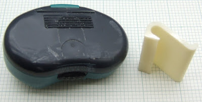
My wife is a very measured person. As well as watching how much power we using she likes to count her footsteps with a pedometer to check if she is getting here daily quota of 10,000. I have bought her several pedometers but they generally come to an early demise due ti inadequate belt clips. The last one fell into the toilet! The first one I bought was the best, but the belt clip broke off.


I promised to RepRap a new clip a long time ago, but only got round to it today. Neither of us could remember what the old clip looked like so I designed a simple one from scratch. To my surprise it printed perfectly on the hot bed, I thought it might need some cooling. HydraRaptor will have automatically dropped to half speed because the layers are so small.


I cut off the remains of the old clip and filed it smooth. I then removed all traces of grease with some isopropanol and welded it on with some MEK pipe cement. A friend gave me it anticipating that I might want to weld ABS someday. It will dissolve and weld ABS and PVC. I think the case is ABS, so it is ideal for the job. It needs 4 hours to cure, so I left it overnight.

It seems to have done the job. I offered to make it in black but my wife wasn't bothered.


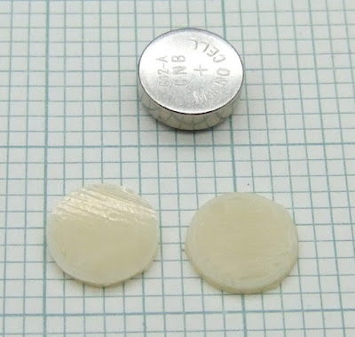
The next problem was that the batteries had gone flat in the years she has been waiting for me to fix it. Buying specific batteries is expensive but you can get a mixed selection of 40 for £1. The problem is though that we mainly use the biggest ones so have too many of the smaller ones. I had some that were the right diameter but too thin so I Reprapped some spacers.


I can now make objects side by side one layer at a time with no strings between them. These are probably the smallest things I have made. They are about the size of tiddlywinks.


A bit tricky to keep in place while the battery cover is replaced but they did the job.


So I am back in the good books for a while. I managed to run off two of these as well. They take about 90 minutes each and are perfectly flat and string-less again.


Just the odd lump on the surface at the start or end of an outline. I think that can be easily solved by always starting on an inner shell before doing the outer shell and then finishing the outer shell with a wipe towards the inner one.

Sunday 10 January 2010

Golden wonder

My first attempt at extruding ABS onto hot Kapton had "all the stops pulled out" to make it stick, i.e. 120°C bed, nozzle height 0.1mm too low, very slow outline and infill on the first layer (4mm/s). The adhesion was very good so I decided to back off a bit. It is not a good idea to change more than one thing at a time but I did anyway. I got rid of the -0.1mm Z offset and sped up the first layer infill to 32mm/s, leaving the outline at 4mm/s. I also dropped the bed temperature to 80°C. That was too low, the corners lifted about 1mm during the build, but I think the part will still be usable.


The base is still glossy but you can see and feel some valleys between the extrusion "lanes". The next test was a binary chop with the bed at 100°C.


This is perfectly flat, even when off the bed for a day, but the extrusion lanes are still noticeable. The next test was at 110°C.


The extrusion lanes are gone in most places but a few are just visible. The first one that I did at 120°C has no extrusion lanes on it all, just some very slight graining from the Kapton tape that you can also see on the picture above. The tape lines and grain go from bottom right to top left. The extrusion infill slopes bottom left to top right and is only visible on the right hand side of the object. I think perhaps Z has to be a bit lower to get rid of them completely, but it is only important if you want to make something aesthetic, like an instrument panel, for example.

Of course there are the tape join marks. I used unbranded polyimide as it seems to be about half the price of branded Kapton. I got it from here, which is very cheap and free shipping if you don't mind waiting a while. You can get polyimide tape up to 250mm wide, but it is always on a 33m roll, so it gets very expensive. I have ordered a 150mm roll to cover the working area of HydraRaptor's build table. It was £53.71 from here, so very expensive, but a small price to pay for perfection! I don't know when it will arrive as post is a nightmare at the moment. I am still waiting for things from the 17th of December. Parcels are not being delivered because of the snow, so you have to go and collect them, but several letters and packets seem to have disappeared.

Here are all the tests side by side, notice the colour change with temperature, it is a bit exaggerated on the photo : -


I now have a full set of Mendel vertexes including two that I made in PLA that warped slightly (on a cold bed). I moved onto something more ambitious on the warping front: the Mendel x-carriage-lower_1off part. I don't think this is printable in ABS without a heated platform, or air stream, unless you use the apron method developed by Forrest Higgs. For this test I started the bed at 120°C and dropped it to 100°C after the first layer. The logic being that 100°C seems to be enough to prevent warping, but 120°C is needed to get a perfectly smooth finish. It takes a few layers before the temperature has dropped to 100°C as I don't wait for the plate to cool down.


Unfortunately the ancient version of Skeinforge that I use gets one layer wrong on this part. The layer has the central hole missing. The filament didn't span the void very well as it is a very big void, I have no fan running and there is a lot of heat rising from the bed. That caused some filament to stick up and collide with the head. It spun round 90° unscrewing it 1/4 of a turn. Amazingly it did not leak but the nozzle hole must be slightly off centre with respect to the barrel thread, so I got an offset in X and Y above the layer that went wrong. Still, the objective was to test warping and it came out totally flat.


The corners have a dimple that looks like an air bubble, but must be something to do with them trying to lift I think. Apart from these the base is as flat as glass and had it not been for the Skeinforge bug it would have been usable straight off the bed. I cut the membrane out with a knife and drilled through the blinded holes before taking these pictures.


I tried the x-carriage-upper_1off starting the bed at 120°C for the first layer and dropping to 90°C. Again Skeinforge got it wrong, not surprising as the topology is very similar. This time I also dropped the filament temperature to 220°C, so it spanned better and the head did not get spun. A longer snout on the nozzle might be a good idea to avoid collisions with build defects.


Again here it is with the membrane removed.


The corners lifted very slightly but the rest of the base is completely flat. It doesn't rock on a flat surface like an object made on a cold bed would. In fact, the raised corners made it easier to remove from the bed.


So it looks like 100°C bed temperature is the minimum to prevent warping when using Kapton. 120°C for the first layer gives a better aesthetic finish, perhaps with a small negative z-offset. Having the object kept warm seems to allow a lower filament temperature without losing strength. I used to build at 240°C and use 0.5mm for stronger objects. I can now use 220°C and 0.4mm with no sign of de-lamination so far. The lower temperature is good because the ABS out-gasses less and so smells less.

I can't recommend Kapton on heated aluminium highly enough. It has transformed my experience building with ABS completely. I no longer need a raft, which saves a lot of plastic, time and labour to remove it. My objects can be completely flat, smooth and glossy. Together with using a geared stepper extruder drive to completely eliminate ooze it means I just print an object, remove it from the bed and it is ready to use. There is a slight meniscus of plastic around the base, which you might want to remove with a file or a knife.

It has several advantages over acrylic: -
  • Acrylic is a good insulator, so even 3mm reduces the surface temperature by about 15°C, making it take longer to warm up and harder to control.
  • It tends to warp as it has a similar glass transition temperature to ABS.
  • It can be hard to remove the object as it can be permanently welded if you deposit the ABS hot enough.
The way ABS sticks to hot Kapton is different. The Kapton does not melt at all so you don't get a weld no matter how hot the ABS is. I don't know what sort of bond it makes, but it is always peel-able.

While I have been writing this article a friend came up with a brilliant suggestion. Why not use non-adhesive Kapton film, clamp it on the table, possibly with a vacuum? When the build is finished just release it so it can be peeled off the object with ease. I realised that would enable a conveyor belt table to be made. People have suggested this would allow a machine to churn out parts unattended. E.g., stretch a band of Kapton over a heated plate and rotate it when the object is finished and has cooled. The object will then drop off the end.

I still have a couple of problems to solve with the heated bed. The heat spreads downwards and warms my X-Y table. It is not much, I haven't measured it but I would guess to mid 40's C. That is enough to expand the aluminium that the table is made from and open up a gap in the ways so that it has some play and starts rattling. I removed the foam-board to leave an air gap (the logic being that the movement of the table would generate some cooling airflow) and covered the top of the bed with aluminium foil to reflect the heat back. That helped, but not enough. I think I will need to blow cold air over the top of the table with a sheet of something like PTFE to cover the bottom of the heated bed.

The other issue is that having heat around the object rather than cold air blowing on it means that void spanning and overhangs don't work as well as they did. I think I need a jet of warmed air directed at the end of the nozzle to cool filament to freeze it quickly.

Tuesday 5 January 2010

Hot metal and serendipity

I couldn't get to work today because we had seven inches of snow during the night and a couple more today, so I had an extra day of RepRapping.

So my extruder is back working after re-fixing the thermistor with some RTV silicone. I get a degree or two more temperature swing with silicone compared to Cerastil, so not ideal, but it is workable. I think the plastic has such a high specific heat capacity and thermal resistance that it probably averages out the temperature swings anyway.

I switched to ABS to make a change from PLA as I am now able to use my 5kg spool of oval ABS that has always been two wide for my previous extruders. The bore of this one is 3.6mm, which is actually a bit on the big side for 3mm filament. I think about 3.3mm would be the best compromise.

My first experiment was to see if I could extrude directly onto my heated aluminium bed. My initial attempts failed to stick, even at 110°C, but I found that I could lay down a raft. I always cool the raft before applying the first layer of the object (I also drop the temperature of the first layer to 190°C), otherwise it welds too strongly to remove. When I cooled the raft it detached from the bed, presumably because it shrinks.

I reasoned if I could get the raft to stick then I should be able to get the object to stick. The difference is I do the first layer of the raft at 4mm/s and have the head lower than I would normally, so that the filament is squashed more. I tried making the first layer of the object at 4mm/s and a little lower than it should be. It almost worked so I upped the temperature to 120°C and tried again. This time I was able to make one of Zaggo's whistles.


When it came to making the pea it got too hot and started moving around.


Normally I would use a fan on ABS to get small items to hold their shape, but obviously blowing cold air onto a hot base is going to waste a lot of power. The fix I have in mind is to blow a very small jet of air at the same temperature as the base and aim it just below nozzle. Hopefully by keeping the jet small I can avoid the sort of power that hair dryers use. Adding the heated bed has increased the power consumption of my machine by about 50W, which has more than doubled it.

When I cooled the finished object and the bed to 40°C, by running the fan, the object simply lifted off. At 120°C the ABS is like a soft rubber or gel. It clings to the aluminium, but will peel off with very little force. When it cools it becomes completely detached.


The bottom of the object is smooth and shiny and perfectly flat. I can actually see part of one of the swirls that are on my bed if I catch it right in the light. That means the plastic takes the texture of the base, so you could pattern and texture it in the same way as injection moulds.

The next thing I tried was a Mendel vertex bracket as these are big enough to warp. It managed the outline, but when it started doing the outlines of the holes the filament failed to stick so I aborted that build.

The obvious way to get more grip is to use a sheet of acrylic as many people report that works well. I have a couple of problem with that though. Acrylic is a good insulator so the temperature control becomes more difficult. It tends to warp unless it is held down at the edges. I don't have any bolts long enough to mount it on my bed with the frame on top. I ordered some 2BA studding last year, but all the post from just before Christmas has gone missing.

I looked around for a piece of metal with some texture and found some aluminium with a satin finish painted with metal primer, from a very old experiment. It looked promising to start with: -


But it soon snagged and started ripping it up again: -


However, as you can see, I held the plate down with Kapton tape and by accident part of the object was extruded onto the tape. It stuck well to the Kapton but was peel-able. This looked extremely promising. Kapton on top of aluminium could be the perfect bed material for ABS. It looks like it will be reusable many times, as masking tape is for PLA.


The bracket stayed perfectly flat during the build. I cooled it with the fan to 40°C. It was quite difficult to remove. In the end I put a penknife under one edge and tapped it with a hammer. It came off cleanly and with a perfectly flat base with a glassy appearance.


The only blemishes are the gaps in the tape, what looks like an air bubble in the tape, and the dent from my penknife.


The base is a slightly golden colour and that extends up for the first few layers so I think the bed was a bit too hot. I had it at 120°C and the first layer at 4mm/s, so I will have to back track a bit and see if I can get away with a lower temperature and faster first layer, but this is looking very good. No warping, no raft, a cheap reusable bed material and a mirror finish.

Sunday 3 January 2010

Extruder broke already

Well my best attempt at making a reliable extruder again resulted in one that only lasted a few weeks! The brass worm pulley that was pushed onto a splined shaft worked loose while extruding PMMA.


PMMA is quite hard work to extrude, but probably no worse than HDPE. On reflection splines into brass are not going to hold the massive force that occurs at 2mm radius. A better idea would be to have a boss on the side of the pulley and use a set screw onto a flat on the shaft. I would also add smaller diameter bosses at each side to meet the centre rim of the bearings. That would automatically position the pulley dead centre.

But to do that I would have to make a new pulley cutting jig and redesign the motor bracket to be a bit wider. I would need a working extruder to make the new bracket of course, so I decided to bodge the existing design.

I drilled out the centre of the pulley to 6mm and then reamed it to 6.4mm. I then turned a steel hub from a piece of hex pillar. I made it about a tenth of a millimetre oversized, added a chamfer to the hole in the pulley and forced it in with a vice, creating a very tight fit.


I didn't trust that to hold on its own so I left a hex flange on the other side and soldered it to the brass: -


Certainly not my best soldering, but bodging is bodging. The hub is twice as wide as the wheel and steel is harder than brass, so it should have a much better grip on the splines. I don't know if it will last or not. The constant back and forward motion of the anti-ooze fix means that if anything is weak it gets worked loose.

With the repaired extruder I made a third lamp shade clip leaving 1mm of the acrylic rod left above the pulley, how lucky is that?


Then I pushed my luck too far. When I bought the 3mm PMMA rod I also got a 2mm rod to compare results. Stiffness of a rod is a fourth power on diameter I think, so 2mm filament is five times more flexible than 3mm.


This would certainly be feasible to use in coils as it has a similar minimum bend radius to 3mm PLA, we just need to find somebody to supply it in that form at a reasonable price. 2mm rods are even more expensive than 3mm rods, £1.24 on eBay as opposed to £1.49, but are only 44% of the volume!

I decided to give it a try in my newly repaired extruder by printing a whistle. I had to scale it down because with 0.4mm filament it would use more than 1m of 2mm filament, so I printed the same g-code using 0.3mm filament and scaled the dimensions accordingly.

It managed to print a couple of layers and then the extruder jammed. I think the problem is that with a 3.6mm bore and 2mm filament there is too much of a gap, so molten plastic can flow upwards and freeze in the cold part of the tube above the taper. I think it would work fine with an extruder designed for 2mm filament. The drive mechanism just about works because although it does not have as much grip, it only needs 44% of the force that 3mm filament needs. The barrel and heater block would need a smaller bore though and could be made smaller. Similarly the smaller motor I used before would have plenty of torque, in fact a high torque NEMA14 should work.

So there are a lot of advantages to using 2mm feedstock like commercial machines do, BUT stiffness falls as a forth power, but force required only falls as a square law, so I expect soft plastics like HPDE, PP and PCL may buckle when being fed. Certainly the gap between the pinch wheel and the barrel entrance would need to be very small.

I fixed the jam by putting a drill down the hot barrel and hitting it with a hammer. That fixed it and I hand fed some ABS before reassembling the extruder. After assembly it would not work at all. The thermistor had shorted out to the metal work!

Nothing much to see from the outside, just a weird furry slimy deposit on the back of the AL tube and a green stain on the thermistor lead that was shorted.


I cannot get to the thermistor or heater without removing the PTFE cover, but that can't be removed without unscrewing the barrel, another slight design flaw. If I had tapped the stainless steel pipe all the way up I could just unscrew it from the AL tube that surrounds it, but it is really hard work tapping stainless steel.

I unscrewed the barrel while the extruder was hot to reveal this mess: -


The plastic that leaked when I first built the extruder has been stewing for weeks and has boiled down to something resembling bitumen. I expect the more volatile products condensed on the cold AL tube above it forming the Vaseline like deposit.

I couldn't tell why the thermistor was shorted because it came away with the PTFE cover. The Cerastil that I glued it in with seems to have decomposed in the chemical soup around it. My last few attempts at sticking thermistors with Cerastil have not been very successful. I am not sure if I mixed it to the wrong consistency, or if it is now too old to cure properly. It doesn't look any different, but instead of rock hard cement I seem to get something crumbly.

I cleaned it all up and stuck the thermistor back in with RTV silicone. I am sure it is not as conductive as Cerastil, but over such a short distance (between the thermistor and the wall of the hole it is in) I am hoping it will not have much effect.

I made the hole for it a bit deeper and opened out the top so it was big enough to accommodate the PTFE sleeving as well. That should keep it from touching the metal. It is surprisingly difficult to glue something into a small hole with a viscous glue. It is hard to get the glue to go down the hole without leaving an air pocket. A better idea might be to drill out a small screw, all the way through, fill it with glue from both sides. Then when it has set simply screw it into a tapped hole in the heater block.

I am waiting 24 hours for the silicone to cure now, so back to work tomorrow and less blog posts.