Friday 28 December 2007

To raft or not to raft?

When extruding HDPE onto foam board a raft needs to be laid down first to increase the anchorage at the corners to reduce curling. It becomes part of the object and has to be trimmed back to its outline with scissors or a knife. Now that I am extruding onto polypropylene cutting board I wondered if it was still necessary.

The temperature at which I lay down HDPE onto the cutting board is important. At 180°C it does not stick. At 200°C it sticks well but can be peeled off with the help of a penknife. Higher temperatures make it harder to remove and do more damage to the board.

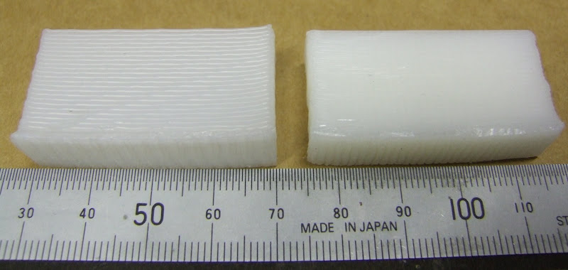
Here are a couple of 15mm test cubes made directly onto the PP board without a raft :-


The one on the left had the first layer extruded at 200°C and subsequent layers at 240°C. As you can see it curled badly, particularly at one corner. The one on the right had its first layer extruded at 220°C. It looked promising but when I tried my standard warp test block the result was not good!


So it looks like the raft is here to stay. Here is an example :-


I lay down the raft at 4mm/s with a notional filament diameter of 1.1mm with the extruder head 1.3mm above the board. This is to get the filament as round as possible so that it doesn't form a solid weld. In actual fact, gravity causes it to slump to about 0.9mm high and spread to 1.3mm wide. The oval area calculation would give 1.34mm and a pitch of 1.3mm is sufficient to get adjacent filaments to stick together. My rationale for making the raft as thick as possible in one layer was to make it strong without taking too much time. It probably does not need to be as strong now that it binds to the PP.

I put the raft down at 200°C, then I do the first layer of the object at 240°C with the fan off to ensure it welds to the raft and then subsequent layers at 240°C with the fan on.

I calculate the amount the raft overlaps the object with this completely arbitrary function :-
def overlap(x):
return x + 10 + 10.0 * (x - 20) / 80
I halved the overlap when I went from foam board to polypropylene.

Thursday 27 December 2007

Cutting corners

When making solid blocks with 0.5mm HDPE filament I noticed that the corners are not very accurate. The right hand edge of the 20mm cube below shows this effect at its worst :-


The problem is that, although the machine makes a perfect right angle, the filament appears to have a minimum bend radius and so cuts the corner. The amount it cuts the corner seems to vary from layer to layer giving rise to the rough edge.

I think the variation is due to the fact that my extruder spindle is a bit off centre. This causes the torque to go up and down as it rotates, which causes the flexible drive cable to wind up and run down again. This causes speed variations despite the fact that the motor speed is well regulated. At some point I will get rid of the flexible drive.

I expect the fact that I am stretching the filament doesn't help with the corner cutting. I improved it a lot by slowing down the drawing of the outline to 4mm/s and leaving the infill at 16mm/s. Here is the result :-


Still not perfect, another thing to try would be to recognise that there is a minimum corner radius and make the nozzle follow an arc of that radius around the corner. At least that way it might be more uniform.

Here is a close up of the top face taken with a scanner:-


As it goes round the corner the filament has an external radius of about 1.5mm and an internal radius of 0.9mm. As it is 0.6mm wide that is probably not bad. You can also see that the zigzag infill sometimes ends a bit short of the edge, probably also due to corner cutting.

To get sharper corners I expect I need to use a nozzle with a smaller hole, so that the filament can be fine without having to be stretched, but that has the disadvantage of slowing down the extrusion rate for a given pressure.

Wednesday 26 December 2007

Warped

Having got an idea of the HDPE warping for thin walled open boxes, I decided to start investigating solid shapes. I made a solid block 40 x 10 x 20mm to compare with the open boxes of the same dimensions.


Obviously there are many ways to fill the interior so I started with the simplest, just alternate layers of horizontal and vertical zigzags. HydraRaptor seems quite happy extruding 0.5mm diameter filament at 16 mm / second. If extruded into free air it would actually be 1mm at 4mm/s, but that is too course, so I move the head at 16mm/s which stretches it.

From trial and error I have found that a good layer height to use is 0.8 times the notional filament diameter. If it is more, then as the lower layers shrink, the nozzle rises faster than the object and a gap develops. Once that happens the filament squirms about and does not follow the path of the nozzle accurately.

So the extruded filament is constrained to 0.4mm high. Measurements show the width to be about 0.6mm. Incidentally, if it squashed to a perfect ellipse with a height of 0.4mm then it would be 0.625mm wide to have the same area as a 0.5mm circle. I extrude the zigzag with a pitch of 0.6mm so that adjacent filaments touch, but it means the object is not actually completely solid. The space occupied by each filament is a rectangular channel 0.4 x 0.6 = 0.24mm² but the cross sectional area of the plastic is π x 0.25² = 0.20mm², so about 18% is air. I confirmed this by weighing the block. It weighs 6.5g but if it was solid HDPE then 8ml would weight about 8g. It takes about 45 minutes to make the object including laying a raft.

Before I tried it, I always imagined the amount of plastic deposited would have to exactly match the volume of the extruded object otherwise it would sag or bulge. I could never understand how FDM worked reliably. Now I know that the volume can be a bit less and the difference is made up by air. That means the amount of plastic deposited is actually not that critical, which is why RepRap can get away with an open loop extruder.

I measured the warping with the three nail jig that I showed in the last post. The thin walled box is warped 0.44mm and the solid box has warped 0.87mm so that answers the question whether solid objects warp more or less. Note that the thin walled box is made with 1mm filament because 0.5mm filament is too thin to be self supporting.

I expect I can make a less warped block by extruding a thick base and then a less dense infill above that. Something else to try.

It is amazing how strong 10mm thick HDPE is. You don't often get to see plastics in that form. Most end products have optimised strength against cost by having thin walls and ribs etc.

Sunday 16 December 2007

Chopping up chopping boards

Up until now I have been extruding HDPE onto foam board because it was the only thing that it sticks to well enough. However, it has a couple of failings: It is not strong enough to completely resist the warping caused by the HDPE and it is not reusable because the surface gets ripped off.

I have tried many other surfaces including various woods and metals (with and without primer), melamine and several other types of foam board but nothing worked. Obviously HDPE sticks to HDPE so I decided to investigate that further.

My first idea was to use a thin sheet of HDPE cut from a milk bottle. This makes a nice surface to extrude onto but the problem is holding it down. I first stuck it down with double sided tape but the heat melts the glue. Sticking it to a sheet of aluminium to take the heat away improved matters and I was able to get slightly less warping than with foam board.


To compare the warping on different base materials I made a test shape that is a 40mm x 10mm x 20mm open box with 1mm walls and measured how much the corners lift using a simple jig.


With foam board I was getting 0.83mm lift between corners and the middle. With HDPE stuck to aluminium I got 0.76mm. Not much better because the glue of the sticky tape stretches under the curling force.

I needed a thick HDPE base and I had heard that plastic kitchen chopping boards are made from HDPE. I bought a new one from ASDA which looks like this :-


It is 5mm thick, opaque and quite rigid. I realised it was very different from the other chopping boards we have which I think came from IKEA.


These are 10mm thick and made from a softer, more translucent plastic. To find out which was HDPE I used the flow chart on this website www.texloc.com/ztextonly/clplasticid.htm. I concluded the thin hard one from ASDA is HDPE and the thicker softer one from IKEA is PP. HDPE seems to stick equally well to both of them but the HDPE one warped a bit when it was only held down with masking tape, so I decided to go with the PP one. I cut it up and bolted it down to my XY-table. It was a bit curved due to years of dishwasher use but bolting it down pulled it flat.


Surprisingly, if I lay down a raft at 200°C it sticks well but can be easily prized off again with a penknife. The board is marked slightly but it can be reused over and over again.


I extrude the object at 240°C so that it welds to the raft and itself, and I turn the fan on after the first layer so that the object cools to room temp as fast as possible.

The board is strong enough to hold the object completely flat while it is attached but when it is removed it does still curl a bit. I measured 0.44mm on my jig so that is about half the curling I was getting with foam board. Other than extruding onto a convex surface, I think that is the best that can be achieved for that shape with HDPE at room temperature. Here are the three tests side by side :-


Next I will look at different solid shapes to see if they warp more or less.

Tuesday 13 November 2007

Disaster recovery

I am pleased to say HydraRaptor is now back up and running after my accident where I connected 240V to a 3.3V logic input. I had to replace most of the electronics, which is annoying because I originally made it out of things I already had, so it cost me nothing, but replacement parts cost me around £180 and obtaining them set me back three weeks.

Things that were destroyed:
  • My ADSL router: a friend kindly gave me a replacement.

  • My PC's serial port: I replaced it with a USB to serial adapter.

  • The Freescale DEMO9S12NE64 evaluation board that I used for my axis controller: next day delivery from Farnell.

  • The EZ430-T2012 eval board that I used for the extruder controller, fortunately the spindle controller was not connected at the time so that survived.

  • The ULN2803 and 7407 chips on my interface board.

  • The optical shaft encoder chip on my extruder.

  • The NEAT MDM7 stepper driver on the X axis. The only thing wrong with it was the direction input was not working. They are opto coupled so it should have been just a simple matter of replacing the opto, but the whole thing is potted in epoxy resin so it is impossible to fix. I managed to find a replacement on the web and I have got some spares on the way as well.

Things that survived:
  • Both power supplies and all the local voltage regulators.

  • The Y axis stepper driver.
  • The X-Y table shaft encoders and Hall effect limit switches.

  • The protected MOSFETs on the extruder controller.

I spent the time waiting for the stepper controller to arrive from the US improving my firmware. I fixed a long standing issue with timing: I was doing my Ethernet comms under interrupt and the stepper motor timing with a higher priority timer interrupt. Unfortunately, the 9S12 does not have nested interrupts, so the interrupt priority is pretty meaningless. I fixed it by moving my comms to the foreground as the machine has nothing else to do in the foreground but process commands coming from the network so there was no point in doing it with interrupts.

I also added acceleration and deceleration to my stepper driving software. I am aiming to lay down 0.25mm filament at 64mm/s. My XY table can easily move that fast but I didn't like the thump I was getting when it started and stopped. It's a bit much to ask it to accelerate a few kilograms to 64mm/s instantly! The datagram for the goto_xyz command now includes a table of delays to use for the first and last n steps. It remains to be seen how much distortion I will get from not moving at constant velocity. At the very least the acceleration will be useful in speeding up the moves when it is not extruding.

Saturday 27 October 2007

Extruder dimensions

I have been asked for dimensioned drawings of the extruder. I made these by manually inspecting the 3D models in ArtOfIllusion. It is not the easiest application for extracting dimensions so I made 2D drawings in Visio which does have good dimensioning tools. I then made Python scrips to do the milling. My dimensions may differ in places but I did make the extruder from these drawings and it does work. I tightened up some of the hole clearances because my milling machine holds much tighter tolerance than FDM.

This is the motor shaft coupler. I adjusted the slot to suit my GM3 motor. I think there are now two versions of this part. The official design is tapered but this is not necessary with the offset motor mount so I simplified it to a cylinder.


Here is the finished article milled with a 2.22 mm bit. The step on the outside and in the shaft slot are there because my milling tool's shaft is wider than the bit, so to go deeper than 9mm I need to have some clearance. The material is some sort of metal loaded resin.


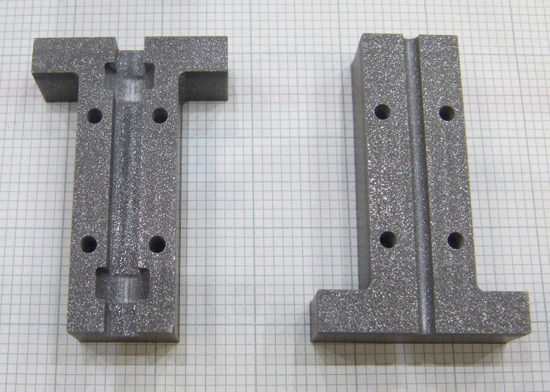
Here is the clamp drawing I used. It has now been superseded by a larger design. Note that I adjusted the hole for the PTFE to suit my 12mm rod. I think the official design was 10mm but is now 16mm. I also widened the slot to allow the 2.2mm milling tool to get in and added some extra mounting holes to suit my machine.


I milled it from 9mm Delrin.


Here is the pump drawing :-


The poly channel on the official version slopes outwards at the entry but that is only needed for the version without the offset motor.

And here is the milled version :-


The material I used is not as slippery as CAPA so, to reduce friction in the channel, I smoothed it with emery paper, polished it with metal polish and sprayed it with PTFE dry film spray.

I split the motor mount into three pieces for milling from a sheet of 5mm perspex. I fixed the pieces together with M2.5 screws, tapped into the perspex.


If anybody wants the Visio source file it is here:- forums.reprap.org

Tuesday 23 October 2007

They don't like it up 'em!

How is this for bad luck :-

I was trying to connect a scope probe to the far side of a two row connector on my machine. I made a small hook from a piece of wire with a bit of insulation to get it past the front row.


I inserted this with the power turned off. Unfortunatly, and almost unbelievably, the far end of the wire manage to find its way into a hole leading to the mains live terminal on my solid state relay. That was the only thing on the live side of the mains switch.

Massive bang! Blew the crap out of HydraRaptor and my ADSL router. My PC is crippled is well, it no longer runs at the correct front side bus speed and insists I haven't got an 80 pin IDE cable.

This is the CPU of my axis controller :-


And this the micro from my extruder controller :-


I expect all the rest of the electronics is fried as well, so pretty much the end of HydraRaptor. The only lucky thing was that I was holding the insulation, otherwise it might have been the end of me as well!

Stretching a point

In his article: x-idler-bracket-continued Vik Olliver alluded to the fact that you can extrude filament with a smaller diameter than the hole in the nozzle. I did some experiments to see how fine I could go. In fact the final filament diameter is simply determined by the feed rate of the extruder and the travel rate of the nozzle, or in my case the bed. The filament stretches to the length that matches the rate of travel while it is still liquid. You can then calculate the mean diameter from the volume of material extruded. The nozzle height has to be a bit less than that mean diameter and then the width becomes a bit wider.

Here are three 20 x 20 x 20 open cubes with different wall thicknesses :-


The first was 1mm diameter filament extruded at 4mm per second with a height of 0.8mm giving a wall thickness of about 1.2mm.

The second was the same feed rate but with the extruder traveling over the bed at 16mm per second to give 0.5mm filament, the same as the nozzle hole diameter. The height was set to 0.4mm giving a wall thickness of about 0.6mm. As you can see it warps more but I expect it would behave if it was building a solid object. The bottom layer which was stuck to the table has better corner definition.

The third attempt was 0.35mm filament extruded at 16mm per second with a hight of 0.28mm and a width of about 0.5mm. As you can see holes started appearing but I think that was just because the sides buckled so badly. Interestingly the holes can be bridged by filament above that needs no support. Again, I think this would be OK making solid objects, or at least objects with thicker walls.

This is really good news as it means I can get down to the sort of resolution commercial machines get (0.25mm) without having to have a very small nozzle aperture, which would limit the flow rate. It remains to be seen what effect stretching has on the polymer but as it is still liquid at that point I think it wont increase the contraction much, if at all. It does mean I need very fast head movement to keep up the deposition rate, about 64mm per second. I think my machine will do that if I reconfigure the steppers for speed rather than torque, a simple one wire change.

Tuesday 16 October 2007

Scaling new heights

In my article laying-it-on-the-line I showed how I arrived at this test shape, a 20mm open ended cube :-


I decided to try different sized shapes to see how the process scales. It turns out that it doesn't and 20mm cubed is the magic size that is easiest to make!

The first thing I tried was taller :-


As you can see at 50mm tall it is starting to sag and 100mm is hopeless. The problem is that as the height increases, the plastic already laid down contracts as it cools and leaves the nozzle high and dry. I fixed that be reducing the Z increment from 1mm per layer to 0.95mm. That allowed me to make a good 20 x 20 x 95mm square tube :-


I presume with this increment I can keep going up, but who knows, I thought that at 20mm!

Next I tried low and wide. This was an attempt to make 120 x 120 x 20mm :-


I stopped it when the first two layers failed to weld. This was because with an object this large, by the time it has traced the perimeter to start the next layer, the first layer has cooled down to room temperature. In my post sticking point I predicted that to make an instantaneous weld between molten plastic and plastic at room temperature requires the molten plastic to be at temperature

T = 2 x Tm - Tr, for HDPE and 20°C this means about 240 - 250°C.

I set my extruder to 240°C and made this mess :-


I don't like running the extruder that hot because, although HDPE is not supposed to burn until 350°C, it smells like burning plastic and the end of the nozzle is glazed black. Also, the toothbrush that wipes the nozzle is showing signs of melting.

The object came unstuck from the foam board because of the extreme corner curling due to shrinkage. This is a fundamental problem with HDPE and room temperature FDM. HDPE shrinks about 2% when it cools from its melting point to room temperature. Commercial FDM machines use ABS, which has a lower shrinkage, and they keep the work piece in an oven close to the melting point. That means the hot plastic does not need to be so much hotter than the melting point, and most of the shrinkage occurs after the object is complete. The problem here is that the first layer cools and shrinks before the next layer lands of top. The next layer is bigger when it welds on top but then it shrinks, contracting the bottom layer more. Each subsequent layer increases the tension on the layers below. The bigger the object is, the worse the effect is because the mismatch between the size of the hot layer and the cold layer below it is bigger in absolute terms.

Following in Forrest's footsteps I tried laying down a raft of HDPE first to anchor the object to the foam base. The raft is 120 x 120mm but the object is now only 100 x 100 x 20mm.


As you can see that gives a big improvement but it wasn't strong enough to hold the corners down fully. A bigger raft, and perhaps a second layer might help but as it was an hour to build the raft and half an hour to build the object I didn't bother trying again. The blob, by the way, is where the firmware crashed on the last layer!

Here are some 40 x 40 x 20mm tests made with rafts, the second one had a bigger raft:-


Here the corner curl with a raft is comparable to the 20 x 20 x 20mm test without a raft showing how this effect gets dramatically worse as width increases.

Next I tried tall thin objects :-


Both were made on rafts and, the first is 15 x 15x x 75 mm, the second is 10 x 10 x 100mm. The photo is not very good but they both flare towards the bottom. The one on the left has an untidy surface as each layer is not well aligned with the layer below it and the one of the right has a completely wavy surface like basket work.

The reason for this is that because the perimeter is shorter, the layer below is still molten when the next layer is extruded on top of it. It moves around giving an untidy surface and also does not resist the contraction of the layer above. The bottom few layers are the correct size because they are welded to the solid raft but the layers above are too small as they have contracted inwards. A 5 x 5mm test shows this effect even more :-


The only way around this is either to wait for the layer below to cool, speed up its cooling with a fan, or extrude very slowly. I decided to experiment with a fan. It was immediately obvious that if you have a fan blowing near the nozzle you have to insulate it otherwise it doesn't reach its target temperature.

The RepRap design uses fiberglass wool but I wanted to be able to see the state of my heater so I decided to make a transparent cover. I started with a plastic test tube, donated by my wife, which used to contain bath salts.


I cut the end off this and drilled a hole to clear the nozzle. I converted a large plastic nut into a mounting flange by stripping out the thread on my lathe so that it was a push fit.


Here it is mounted on the extruder :-


The first fan I tried was a small North bridge cooling fan. It was so light that I could mount it on a stiff wire attached by ring tail crimps and bolts. :-


Unfortunately it wasn't very powerful so the next fan I tried was a PC case fan complete with speed control and blue flashing LEDs.


This worked a lot better but it is difficult to get it as close as I would like it. Here is the tallest thing I have made so far, it is 10 x 10 x 150mm. At this point I changed to 4mm per second travel and a feed rate to give a 1mm filament. I found that you can get finer filament just by stretching it as it leaves the nozzle so the work I did with flow rate and filament size is not really relevant. I had to reduce the layer height to 0.8mm.


This worked well on the windward side, with a nice tight corner, but not so well on the leeward side. The corner away from the fan is more rounded and the layers are less tidy. A cross section shows that the two sides cooled by the fan are straighter and longer.

The 5 x 5 x 20mm test is much improved but its surface area is so small that the fan fails to keep it cool enough. I think the only option with something as small as this is to slow down, and possibly drop the temperature.


Again the leeward side is not as good. The filament short cuts the corner because the layer below is not strong enough to hold it in place. I think to make the fan effective a cowling and duct is needed to get a strong flow of air directed downwards around all sides of the nozzle.


I have noticed that there is always an excess of material at the corners. This is because the head makes a perfect right angle but the filament has a minimum bend radius and takes a short cut. I am not sure how to compensate for this. I can't really pause the extruder because its response is too slow, so I either have to speed the head up as it takes a corner, or perhaps make it move in an arc that matches the bend radius rather than a right angle.

And finally here is an improved version of the magic 20mm cube :-


This is with the benefit of a raft, finer filament and fan cooling. The corners are a bit sharper and the corner curling a bit less. The reasons why this turned out to be the optimum shape are :-
  1. It is small enough that the filament does not cool too much when you go round it.
  2. It is large enough to make it long enough to traverse so that it does not stay too hot.
  3. It is short enough for the fan to be able to cool the back wall from the inside as well as the front.
  4. It is small enough for corner curling to not be too extreme.
From these experiments I now think I have a good understanding of how the parameters: temperature, flow rate, traversal rate, z increment and fan use affect the result. I have only looked at thin walled boxes, I expect solid objects to add more thermal and contraction issues.

The only reason I am using HDPE is that it seems to be the only thermoplastic filament I can buy off the shelf in the UK without getting it specially made.

With a bit of trial and error I expect I could make the machine produce a wide range of shapes and some useful objects but therein lies the problem. It is not supposed to be trial and error. The dream is to be able to input an arbitrary 3D model, of any size within the build volume, and have the item appear a few hours later. At the moment I can't see how that can happen with room temperature extrusion of HDPE. Its melting point is too high and its contraction too great. Managing the temperature of the object being built is very tricky as the features of the object vary from large to small.

Saturday 13 October 2007

GM3 motor suppressor

I have also been asked for more details on my motor suppression circuit that I first blogged in dc-to-daylight, so here goes :-


The Solarbotics GM3 generates large amounts of RF noise from 20MHz up to at least the TV band, which is 470- 850MHz in the UK. I know this because I can see the 20 MHz on my scope and it was also affecting our TV reception.

This is the circuit I used :-


The 1nF capacitors were axial ceramics and the 10nF was a radial ceramic, mainly because that is what I had to hand. I don't know the spec of the ferrite beads because I salvaged them from an old disc drive. Here is what they look like though :-


They should be a low Q type rated for at least 1A. The current rating is not so much about how much current they can carry but about the point where the magnetic field saturates the ferrite and the inductance disappears.

We want them to have a high impedance from 20 MHz to 800 MHz. I don't have much knowledge in this area but think this is quite a big ask for a ferrite and that I fell lucky with these. To get more impedance at the low frequency end it is normal to increase the number of turns to increase the inductance which is proportional to their square. The problem with that is that it increases the capacitance, reducing the attenuation at the high frequency end.

These beads are a good compromise: they have nearly a whole turn compared to a straight through bead which is half a turn, hence four times the inductance, but the wires maintain 0.1" separation so minimizing the capacitance.

The first two 1nF capacitors are soldered to the motor case. This is easier than you might imagine because steel is such a poor conductor of heat compared to copper, although it has to be said I am using a 50W temperature controller soldering iron. I cleaned the area first with a PCB cleaning block.


This is the rest of the circuit before it was soldered on top of the two capacitor leads. Spot my mistake!


Ignore the back emf diode, it is specific to my controller and should really be part of it. I used twin screened cable with the braid grounded at the controller end and left unconnected at the filter end.