Showing posts with label FDM. Show all posts

Sunday, 16 March 2008

Filling in

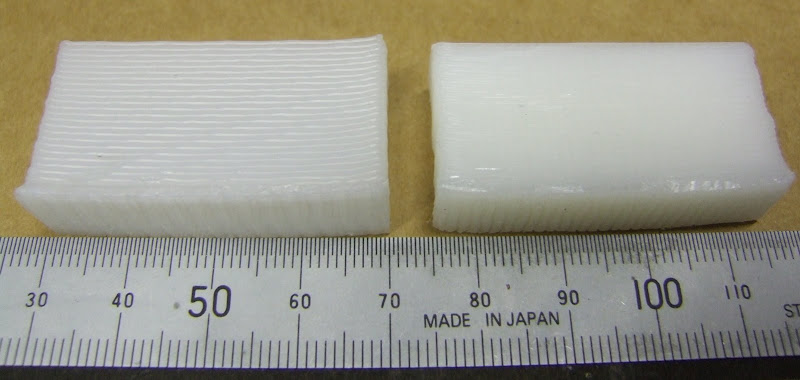
I have been experimenting with various infill patterns. Here is a 40 x 10mm block made with 0.5mm filament at 50% fill: -


For simplicity I used alternating horizontal and vertical lines rather than diagonal. The layer height is 0.4mm so the width is about 0.6mm and so are the gaps. A couple of things that weren't obvious to me at the beginning were: -
The first and last lines of the fill must be adjacent to the outline so that the U turns on the alternate layer above have something to rest on, otherwise they curl upwards or downwards and don't bond to the outer skin. That means adjusting the gaps slightly to make the overall width correct. When the fill is 100% I adjust the filament width slightly to exactly fill the interior. Easy enough with a rectangular object but probably not with an irregular polygon.

The fill lines probably should line up with the those two layers below so that the intersections form a solid column of filament from top to bottom, otherwise some sag may be expected. Again trivial for rectangles but could get tricky to generalise.
Here is 33% fill, i.e. the gaps are about twice the filament width: -


This is 25%. Notice how, although the filament is laid down in a perfect square wave, when it shrinks it pulls itself to the first harmonic. A physical low pass filter!


And here is 20%: -


I found that when putting a lid over the top it struggled with an infill this sparse, so I settled on 25% as the limit for making closed boxes.

All the above are done with filament stretched to 0.5mm. When extruding through a 0.5mm orifice, left to its own devices the filament would be about 1mm due to die swell. I decided to try the same pattern with 1mm filament, i.e. with no stretching: -


As you can see the filament holds the square wave better but what is not obvious is that without stretching it sags a bit in the gaps where it is not supported from below. So some stretching is beneficial, when it comes to spanning voids, but it does increase corner cutting.

As I mentioned before, with my old nozzle, I could extrude 0.5mm filament at 16mm/s. This is what happens with the new one which has an exit hole which is too shallow: -


One unfortunate characteristic of FDM is that errors tend to be cumulative. What I mean by that is if, for example, the U turn of the zig zag fails to bond to the outer wall then that causes the next layer to have nothing to rest on, so that fails as well. The defect then propagates all the way up the object. With 100% fill, any errors tend to have less effect on the layers above.

Rather than slow down my experiments I decided to go to 0.75mm filament at 7mm/s until I make a new nozzle. Here is a 50% fill: -


I also added a bit of overlap between the fill and the outline at the u-turns to get a better bond.

So does the infill density affect warping? I made several test blocks and it looks like the answer is not much. However, I have come to realise that the warping takes hours to fully develop after the object is removed from the base so I will leave them overnight before attempting to make measurements.

Friday, 28 December 2007

To raft or not to raft?

When extruding HDPE onto foam board a raft needs to be laid down first to increase the anchorage at the corners to reduce curling. It becomes part of the object and has to be trimmed back to its outline with scissors or a knife. Now that I am extruding onto polypropylene cutting board I wondered if it was still necessary.

The temperature at which I lay down HDPE onto the cutting board is important. At 180°C it does not stick. At 200°C it sticks well but can be peeled off with the help of a penknife. Higher temperatures make it harder to remove and do more damage to the board.

Here are a couple of 15mm test cubes made directly onto the PP board without a raft :-


The one on the left had the first layer extruded at 200°C and subsequent layers at 240°C. As you can see it curled badly, particularly at one corner. The one on the right had its first layer extruded at 220°C. It looked promising but when I tried my standard warp test block the result was not good!


So it looks like the raft is here to stay. Here is an example :-


I lay down the raft at 4mm/s with a notional filament diameter of 1.1mm with the extruder head 1.3mm above the board. This is to get the filament as round as possible so that it doesn't form a solid weld. In actual fact, gravity causes it to slump to about 0.9mm high and spread to 1.3mm wide. The oval area calculation would give 1.34mm and a pitch of 1.3mm is sufficient to get adjacent filaments to stick together. My rationale for making the raft as thick as possible in one layer was to make it strong without taking too much time. It probably does not need to be as strong now that it binds to the PP.

I put the raft down at 200°C, then I do the first layer of the object at 240°C with the fan off to ensure it welds to the raft and then subsequent layers at 240°C with the fan on.

I calculate the amount the raft overlaps the object with this completely arbitrary function :-
def overlap(x):
return x + 10 + 10.0 * (x - 20) / 80
I halved the overlap when I went from foam board to polypropylene.

Thursday, 27 December 2007

Cutting corners

When making solid blocks with 0.5mm HDPE filament I noticed that the corners are not very accurate. The right hand edge of the 20mm cube below shows this effect at its worst :-


The problem is that, although the machine makes a perfect right angle, the filament appears to have a minimum bend radius and so cuts the corner. The amount it cuts the corner seems to vary from layer to layer giving rise to the rough edge.

I think the variation is due to the fact that my extruder spindle is a bit off centre. This causes the torque to go up and down as it rotates, which causes the flexible drive cable to wind up and run down again. This causes speed variations despite the fact that the motor speed is well regulated. At some point I will get rid of the flexible drive.

I expect the fact that I am stretching the filament doesn't help with the corner cutting. I improved it a lot by slowing down the drawing of the outline to 4mm/s and leaving the infill at 16mm/s. Here is the result :-


Still not perfect, another thing to try would be to recognise that there is a minimum corner radius and make the nozzle follow an arc of that radius around the corner. At least that way it might be more uniform.

Here is a close up of the top face taken with a scanner:-


As it goes round the corner the filament has an external radius of about 1.5mm and an internal radius of 0.9mm. As it is 0.6mm wide that is probably not bad. You can also see that the zigzag infill sometimes ends a bit short of the edge, probably also due to corner cutting.

To get sharper corners I expect I need to use a nozzle with a smaller hole, so that the filament can be fine without having to be stretched, but that has the disadvantage of slowing down the extrusion rate for a given pressure.

Wednesday, 26 December 2007

Warped

Having got an idea of the HDPE warping for thin walled open boxes, I decided to start investigating solid shapes. I made a solid block 40 x 10 x 20mm to compare with the open boxes of the same dimensions.


Obviously there are many ways to fill the interior so I started with the simplest, just alternate layers of horizontal and vertical zigzags. HydraRaptor seems quite happy extruding 0.5mm diameter filament at 16 mm / second. If extruded into free air it would actually be 1mm at 4mm/s, but that is too course, so I move the head at 16mm/s which stretches it.

From trial and error I have found that a good layer height to use is 0.8 times the notional filament diameter. If it is more, then as the lower layers shrink, the nozzle rises faster than the object and a gap develops. Once that happens the filament squirms about and does not follow the path of the nozzle accurately.

So the extruded filament is constrained to 0.4mm high. Measurements show the width to be about 0.6mm. Incidentally, if it squashed to a perfect ellipse with a height of 0.4mm then it would be 0.625mm wide to have the same area as a 0.5mm circle. I extrude the zigzag with a pitch of 0.6mm so that adjacent filaments touch, but it means the object is not actually completely solid. The space occupied by each filament is a rectangular channel 0.4 x 0.6 = 0.24mm² but the cross sectional area of the plastic is π x 0.25² = 0.20mm², so about 18% is air. I confirmed this by weighing the block. It weighs 6.5g but if it was solid HDPE then 8ml would weight about 8g. It takes about 45 minutes to make the object including laying a raft.

Before I tried it, I always imagined the amount of plastic deposited would have to exactly match the volume of the extruded object otherwise it would sag or bulge. I could never understand how FDM worked reliably. Now I know that the volume can be a bit less and the difference is made up by air. That means the amount of plastic deposited is actually not that critical, which is why RepRap can get away with an open loop extruder.

I measured the warping with the three nail jig that I showed in the last post. The thin walled box is warped 0.44mm and the solid box has warped 0.87mm so that answers the question whether solid objects warp more or less. Note that the thin walled box is made with 1mm filament because 0.5mm filament is too thin to be self supporting.

I expect I can make a less warped block by extruding a thick base and then a less dense infill above that. Something else to try.

It is amazing how strong 10mm thick HDPE is. You don't often get to see plastics in that form. Most end products have optimised strength against cost by having thin walls and ribs etc.

Sunday, 16 December 2007

Chopping up chopping boards

Up until now I have been extruding HDPE onto foam board because it was the only thing that it sticks to well enough. However, it has a couple of failings: It is not strong enough to completely resist the warping caused by the HDPE and it is not reusable because the surface gets ripped off.

I have tried many other surfaces including various woods and metals (with and without primer), melamine and several other types of foam board but nothing worked. Obviously HDPE sticks to HDPE so I decided to investigate that further.

My first idea was to use a thin sheet of HDPE cut from a milk bottle. This makes a nice surface to extrude onto but the problem is holding it down. I first stuck it down with double sided tape but the heat melts the glue. Sticking it to a sheet of aluminium to take the heat away improved matters and I was able to get slightly less warping than with foam board.


To compare the warping on different base materials I made a test shape that is a 40mm x 10mm x 20mm open box with 1mm walls and measured how much the corners lift using a simple jig.


With foam board I was getting 0.83mm lift between corners and the middle. With HDPE stuck to aluminium I got 0.76mm. Not much better because the glue of the sticky tape stretches under the curling force.

I needed a thick HDPE base and I had heard that plastic kitchen chopping boards are made from HDPE. I bought a new one from ASDA which looks like this :-


It is 5mm thick, opaque and quite rigid. I realised it was very different from the other chopping boards we have which I think came from IKEA.


These are 10mm thick and made from a softer, more translucent plastic. To find out which was HDPE I used the flow chart on this website www.texloc.com/ztextonly/clplasticid.htm. I concluded the thin hard one from ASDA is HDPE and the thicker softer one from IKEA is PP. HDPE seems to stick equally well to both of them but the HDPE one warped a bit when it was only held down with masking tape, so I decided to go with the PP one. I cut it up and bolted it down to my XY-table. It was a bit curved due to years of dishwasher use but bolting it down pulled it flat.


Surprisingly, if I lay down a raft at 200°C it sticks well but can be easily prized off again with a penknife. The board is marked slightly but it can be reused over and over again.


I extrude the object at 240°C so that it welds to the raft and itself, and I turn the fan on after the first layer so that the object cools to room temp as fast as possible.

The board is strong enough to hold the object completely flat while it is attached but when it is removed it does still curl a bit. I measured 0.44mm on my jig so that is about half the curling I was getting with foam board. Other than extruding onto a convex surface, I think that is the best that can be achieved for that shape with HDPE at room temperature. Here are the three tests side by side :-


Next I will look at different solid shapes to see if they warp more or less.

Tuesday, 24 April 2007

My PolyMorph has morphed!

I now have HydraRaptor controlled by a Python script running on my PC. I decided to test its circle drawing ability in preparation for using it to mill a large hole in the block of material shown in the last post. When I came to refit the pen holder that I made a few weeks ago I noticed it was no longer a good fit. On closer examination it appears to have curled up a bit.


A bit disappointing because I don't like making things twice. Also it doesn't bode well for objects made by FDM, although this was cast rather than extruded.

Saturday, 31 March 2007

Chicken and Egg

The problem with making machines that make themselves is how to make the first one! A bootstrap machine has to be made by hand first. This has come to be known as a RepStrap machine in the RepRap community. Lots of people are trying different approaches using whatever materials are easy to come by locally. Wood, Lego, Meccano, copper pipe and drawer slides have all been used by different RepStrappers. The machine needs three axes of motion and an extruder head to extrude molten plastic filament. Most RepStrap machines use threaded rod as a means of creating accurate linear motion from a stepper motor for the axes.

This was the approach I was planning to take when I started looking at this in mid January. I had a look at how professional CNC machines are put together and saw that the prices are a lot more than I wanted to pay but the accuracy and speed was a lot better than I could hope to achieve with drawer slides, etc. I had a quick look around to see if I could get anything second hand or from the surplus market. To my surprise I found an XY table on ebay for $400 which has a super small step size of 6 um but is able to move quickly and has very high stiffness.


This gave me the idea that I could make a very accurate machine that is also stiff enough to do milling. I found a Z axis on CNCzone for $150 and the project was born.