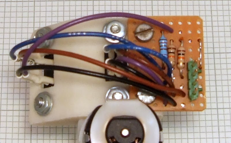
While testing my extruder I found that the filament diameter seems to vary with temperature and pressure. I wanted to investigate this further so I decided to add a shaft encoder to the output of the small gear motor which drives the polymer pump. This would allow me to regulate the speed precisely because the micro would know the exact position of the shaft at any instant.
My first thought was to use a magnetic shaft encoder such as the
AS5035 but then I remembered I had an evaluation kit for some HP reflective optical encoders which I had saved since 1995. HP are no longer in the semiconductor business, that part of the business became Agilent and these chips have been passed on to Avago. The kit had a linear encoder strip, a rotary encoder wheel and three sensor chips.
One of the advantages of magnetic encoders is that they don't need such precise alignment as the optical ones. However, in my case I would have needed to build a raised mounting to hold it over the end of the shaft, whereas the optical encoder can be mounted flush against the gearbox. Here is another bizarre mix of surface mount and through hole components. Can you spot the SMT decoupling cap?

I doubt that I have complied with the strict mounting tolerances but it seems to work well enough for this purpose. Here it is with the code wheel in place :-

Here is what the outputs look like when the shaft is turning :-

Two square waves are produced which are 90° out of phase with each other. This is known as quadrature encoding and it allows both the distance and direction of movement to be determined. I would have expected the mark space ratio to be more equal but it is probably out of spec due to me not meeting the alignment tolerances.
Notice also the nasty glitches on the bottom trace. These are commutation noise from the DC motor despite having a 100n capacitor close to it and using screened cables. Here is what the noise looks like close up without the capacitor :-

And this is the improvement with the capacitor fitted:-

I also tried adding a resistor to form an RC
snubber and adding a ferrite ring around the motor cable, but both made it worse. The only way to effectively suppress DC motors is to mount suppression components directly across the armature windings, i.e. the other side of the brushes.
So stuck with that much noise, it was impossible to use an edge triggered interrupt approach, so I polled the inputs from a fast interrupt and debounced them in software. Here is the code :-
//
// Process the shaft encoder signals
//
#define DEBOUNCE 3
static void scan_optos(void)
{
static byte last_raw = 0;
static byte debounce_count = DEBOUNCE;
byte    delta;

   //
   // Debounce the inputs
   //
   byte bits = P1IN & (SHAFT_A | SHAFT_B);
   if(bits != last_raw) {
       last_raw = bits;
       debounce_count = DEBOUNCE;
       return;                             // Still changing
   }
   if(debounce_count)                      // Still debouncing
       if(--debounce_count != 0)
           return;                         // Not stable long enough
   delta = bits ^ optos;                   // Which bits changed
   if(delta) {
       int dir = 1;
       optos = bits;                       // New state
       if(delta & SHAFT_A) {               // Was it A or B that changed
           while(delta & SHAFT_B)          // If both not scanning fast enough
               ;
           dir = -dir;
       }
       if(bits & SHAFT_A)                  // Work out the direction
           dir = -dir;
       if(bits & SHAFT_B)
           dir = -dir;
       motor_pos += dir;                   // update position
   }
}
This keeps track of the shaft position: motor_pos increases as the filament advances. I then use a timer interrupt to decrement motor_pos at the rate I want the shaft to move at. motor_pos then becomes the error signal for my feed back loop. If it is positive the shaft is ahead of where it should be, if it is negative it is lagging. On-off control was too aggressive so I used
PWM to give proportional control. Here is the code, called from the same fast interrupt :-
//
// Control the motor
//
#define MCYCLE  16
static void do_motor(void)
{
    static int mcount = 0;
    static int on_time = 0;

    if(mcount >= MCYCLE) {                  // At end of cycle?
        if(motor_pos <= 0) {                // If lagging
            on_time = -motor_pos >> 3;      // Set PWM for next cycle proportional to the lag
            mcount = 0;
        }
    }
    else
        ++mcount;
    if(motor_pos > 0 || mcount >= on_time)
        P2OUT &= ~MOTOR;                    // Motor off
    else
        P2OUT |= MOTOR;                     // Motor on
}
This is the resulting PWM waveform and one shaft encoder signal, my scope only has two channels! :-

The speed control works well, no loss of torque as the speed is reduced. It has a bit of a damped oscillation with no load due to the slop in the gearbox but it is fine in the extruder where it has a constant load to hide the backlash.


