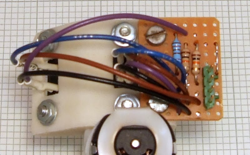
The correct angle for quadrature needs to be (K + 0.5)(180 / n) where n is the number of slots in the wheel and K is an arbitrary integer. The first convenient angle which straddles the bolt through the motor is 45°.

A single coat of BBQ paint seems adequate to block the IR beam.

A bit of a pain to wire up! If it proves to be a useful encoder I will design a pair of PCBs.
The waveforms are now both full amplitude and in quadrature: -

The edges are slow because I am using 4 pin optos, Zach seems to have bought up the world's supply of the five pin ones for the RRRF! The five pin versions have a built in Schmitt trigger to square up the waveform before it goes down the cable. Most micros have Schmitt trigger inputs these days but the disadvantage is that any noise in the cable will advance or delay the edge slightly, giving a timing error. Given the imprecise nature of this encoder I don't think it will make much difference.


I really hope that the accuracy is enough, or at least close. Looking at the photo, with your FFF quality there is enough resolution for some more teeth. My gut feeling is that this must be enough resolution for this application.
ReplyDeleteIf so, this is a wonderful way of making an encoder. We don't need to add any different components (already use those optoswitches). If you make the holes for the optoswitches a little stretched out in one direction you can fine-tune the position of (one of the) optoswitch(s) to fix quadrature offset.
If the wheel is not precise enough, that's not the end of the world. Besides printing an overhead sheet, I think cutting a piece of tin can under a printout. So if you don't have overhead sheets, just print it on plain paper and trace it onto a can with a sharp knife. But I guess the RRRF could stock those overhead sheets easily.
Erik de Bruijn
One more thing:
ReplyDeleteOnce we print a full gear train to replace the solarbotics one for the extruder, we could use the motor-driven shaft (or somewhere in-between) as an encoder instead of the drive shaft. It's not really a priority, but I see it happening in the mid to near future.
Erik,
ReplyDeleteYes I could get a few more teeth on but I thought I would start with the same as Ed's to see if it was good enough. I don't think anybody has written the firmware yet for the one opto version. My guess is the resolution is fine for speed control but not good for accurate starts and stops. My current extruder will apply full power until the motor catches up with where it should be so maximum acceleration at the start but little overshoot because it gets position updates so often. I think with this resolution you may be 0.4mm out with you filament before you get any feedback.
If I could reprap gears, or even just a gear box to put gears into I would use one of the small $7 Jameco steppers and a 40:1 reduction. That would be cheaper than a GM3 and an encoder and a lot more accurate.
Actually I remember another reason for leaving it with 18 teeth: I have good printing resolution already with my 816 step encoder. If this is going to improve Darwins already out there it has to be capable of being made on a machine with less accuracy. Much better if people can improve their machines by downloading and printing new parts rather than having to buy new parts.
ReplyDeleteUsing slots to fine tune the quadrature is not ideal because you would need a scope to do it and the opto needs to be radial otherwise the edges get slower.
Hi Chris. For those without much printing resolution, I've made two accurate optical discs to be printed on overhead sheets (transparencies, the British seem to call them, right?). This is also to be prepared if the quadrature resolution is too low. White paper will probably also work (especially with the Schmidt trigger opto switches) but probably degrades more than you'd like.
ReplyDeleterotary enconder in svg
rotary enconder in pdf
Could you scale it to fit on a toothless STL you might make :)? It probably opens best in inkscape. Scaling with keeping the aspect ratio can be done by pressing ctrl-shift and dragging a lower right/left corner.
Hope you like them!
Has an anyone built a shaft encoder using a conductive gear and metal brushes? Not as beautiful, wears out faster, but maybe a little cheaper.
ReplyDelete