I have started making an extruder for my Darwin but I am running out of ABS. I bought some more from
Tempatron but it is very oval, up to 3.5mm, so it wont fit through HydraRaptor's extruder. So it is a race against plastic to make a new one with a bigger bore! I will try making the filament guide out of HDPE as that is the most slippery of the four plastics I have.
One thing I definitely wanted to try in ABS before it ran out was to make a shaft encoder. The latest RepRap
V1.1 design has one with a single opto but it needs support material and gears. I am happy with the older design now that I have got it to run reliably, so I needed an encoder that mounts directly on the motor. I also prefer two optos in quadrature to avoid errors from backlash and stopping exactly on the edge of a slot. I want to experiment with backing up the filament as well, so I will make this version reversible.
I knocked up a design which uses a pair of slotted optos in CoCreate : -

The wheel is the same as Ed's design except that I have added a boss which mates with the top shaft of the GM3 gearmotor. It has 18 teeth which gives 72 steps per rev with quadrature encoding. One turn of the extruder feeds 0.8mm of plastic with an M5 drive screw. That will extrude about 0.4mm of filament per step, so not great resolution.
When making the opto flags for my Darwin I realised that quite thin walled objects come out OK and are still reasonably strong. I think the bracket is the thinnest thing I have designed so far, its walls are only 2.4mm thick. Its shape really requires support material for the slots and holes but it came out fine without any. It was particularly hairy though when it came off the machine: -

A bit of whittling with a penknife soon cleaned it up :-


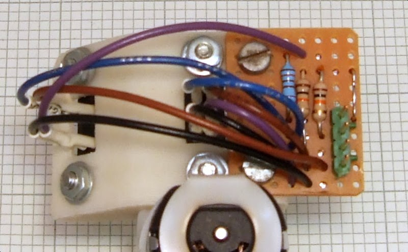
Here it is installed on the motor :-


I wired up to an oscilloscope to test it: -

As you can it is very noisy because I have not made a new
suppressor for the GM3 yet. Also the top trace does not go high properly. This is because quite a lot of IR light gets through the ABS when it is so thin. Not surprising as you can see visible light through it. I painted the top surface black with BBQ paint and that improved it a lot.

I think a second coat on the underside will improve it further. The waves are not in quadrature because somehow I managed to get the angle wrong, so I will have to make another bracket. It will function fine at half the resolution so I might press on with the extruder first.
So a cheap and cheerful shaft encoder, but not very high resolution. Since slotted optos are just LEDs and photo transistors in a bit of plastic, I think I will make another one with the raw components that will be even cheaper. I could put some more teeth on but that would make it harder for people to make and I want people to be able to upgrade their machine with their machine. Another way to do it is by printing onto film with a laser printer. There is a good site about that
here.


