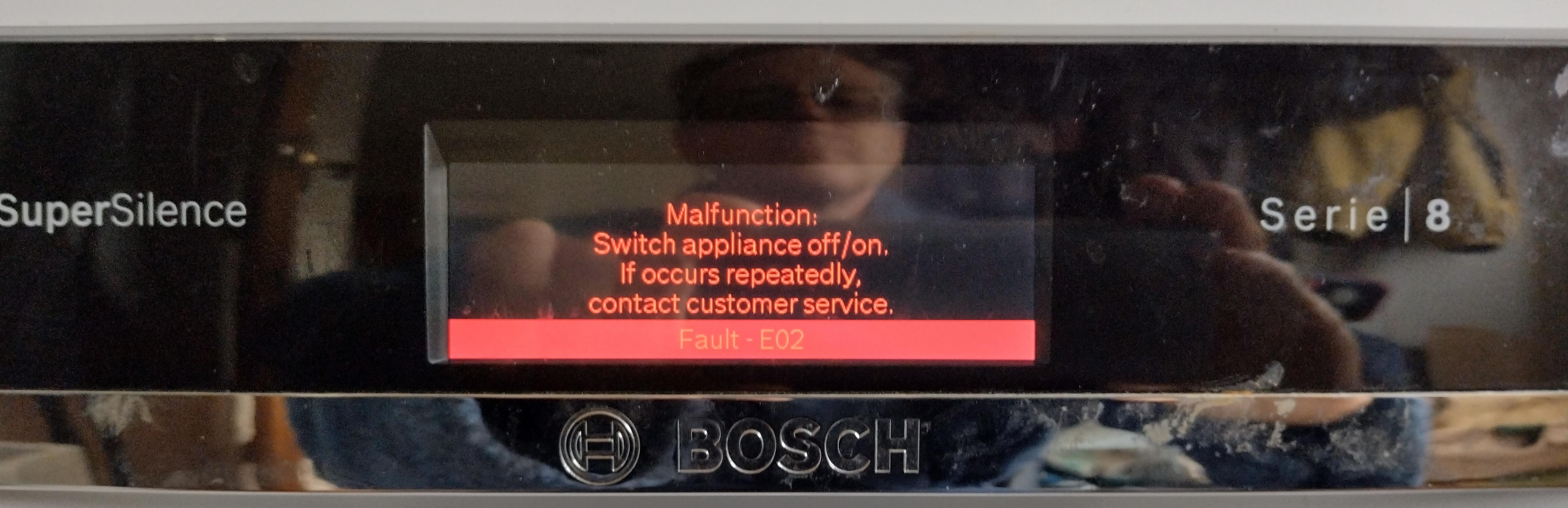
After returning from a long holiday over winter our Bosch dishwasher worked once and then failed during its second use. It came up with this error at the start of the drying cycle and the dishes were cold and not as clean or dry as usual.
I am normally able to diagnose and fix our electronic or electrical appliances, so I set about trying to fix it myself rather than following the advice on the display to contact customer service, perhaps a mistake! I did turn it off and on a few times but it then came up with a communication error.
The model number is SMS88TW01G/01 and we bought it in 2015 for £749 delivered. It was expensive at the time but it normally does a good job washing and drying, is very quiet and energy efficient, so I didn't feel like replacing it.
It turned out to be the longest and hardest repair I have ever done and even involved plenty of 3D printing, so I thought I would document it here in case it helps somebody else. Obviously only attempt something like this yourself if you understand the dangers and do so at your own risk.
I could find lots of YouTube videos for repairing Bosch dishwashers but none for models like this that have the Zeolite drying system. Either they are not very common or don't often break, or are too new to have broken yet.
Googling fault code E02 gives this unhelpful hit on the official Bosch website.
Unofficial repair guides indicate this error is a problem with the heating element, wiring, thermostat or the control board, in particular "the relay". This matched the symptoms as the machine ran cold but the communication error was still a mystery, so I decided to investigate the heating system. I removed the top and side panels simply by unclipping them.
The main electronic control unit is easily accessible at the bottom back right corner of the machine after removing its clip on cover.
The heater connections are the thick red wires and can be probed by removing the connector and inserting 6.4mm spades into the female connector slots. The other connectors are edge connectors directly onto pads on the PCB. They can be probed by putting them over a piece of veroboard as they have the same 0.1" pitch as the tracks.
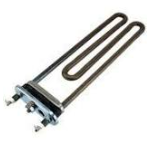
Research with Google informed me that there are two generations of heating system in Bosch dishwashers. The original heater was like a kettle element that the water flows around.
The thermostat was a separate unit that contained a thermistor and a thermal cutout:
The control unit had a single relay and the thermal cutout was wired in series with the element to prevent the water getting too hot in the event of a failure. Simple and straightforward and each component could be replaced separately. However, later models like mine are far more complicated!
The heater is a metal cylinder that the water flows through and has a thick film element printed around the outside. There is no thermal cutout, so for safety it has two thermistors printed or maybe surface mounted onto the cylinder. You can't get just a replacement heater from Bosch, you have to get the whole assembly, which includes the wash pump.
The two thermistors are identical but they have different pullup resistor values at the control unit inputs that feed two analogue inputs on the MCU with two different voltages for the same temperature. So it can detect a faulty thermistor or wiring by working out the temperature two ways and checking they agree.
Instead of a single relay it has two relays, one in live and one in neutral and these are driven by three transistors, one on the +12V to both relays and one in each ground of the relays, so everything is redundant. A single failure will not cause the heater to be permanently on. Seems like a lot of complication just to remove the need for a thermal cutout and if the MCU or its firmware failed it could get too hot. Presumably it has a watchdog as well.
Zeolite models like ours are even more complicated because they have a second heater and a blower fan that draws air from half way up the inside of the wash tub, blows it through a heater, through the zeolite granules and back into the bottom of the wash tub. During the first water heating of an eco cycle the hot air heater is used to both dry the zeolite and heat the water indirectly. The main heater then takes over to get the water to its desired temperature. During the final rinse the main heater gets the water to a high temperature so that the dishes are steaming hot. After the water is drained the blower sucks the moist air from the tub and blows it through the zeolite. The Zeolite absorbs the water vapour and gets very hot due to an exothermic chemical reaction, aiding in the drying.
So there is a third relay and a fourth transistor to switch the neutral to the second heater, sharing the switched live with the main heater. This heater does have a tiny axial thermal cutout in series with it. I don't think there is any other temperature control for it other than the two thermistors attached to the main heater see the water temperature rise when the hot air heater is on. Note the air heater isn't used in the drying cycle, just the blower and the zeolite. It claims to be energy efficient because the heat put into the zeolite while it was heating the water is released when it absorbs the moisture, so you get the water absorption aspect of the drying for free. The vapour will be released again during the heating cycle of the next wash when the dishes are wet anyway and presumably condenses. Some other dishwashers open their door at the end to get rid of the water vapour but that would make your house damp.
Another energy saving mechanism I noticed when I opened the machine is there is large thin water tank over most of the left side of the machine that is filled with clean water at the end of the cycle. So the water for the next cycle is already at room temperature at the start, so needs less heating than cold water straight from the main would.
I tested both heaters and found they had the correct resistance and no apparent leakage to ground or to the thermistors. The thermistors both measured about 13K, which seemed reasonable for a 10K thermistor at room temperature and they had no leakage to ground. I added a cup of warm water to the sump and they both reduced in value by the same amount. I could find no fault with the electrical side, so I decided to turn my attention to the control unit.
On opening, it immediately became apparent that there are two separate control units, the other is the button and display controller in the door of the machine and they are linked by an optically coupled serial bus via the little PCB on the left and this serial comms is presumably what the communication error refers to.
The main controller is not isolated from the mains. The mains gets half wave rectified by a single diode, producing a 340V DC rail relative to mains neutral. This powers two three phase brushless DC motor controllers. One drives the main wash pump motor and the second one is multiplexed between the drain pump and zeolite blower motors by the white relay top centre. This makes the motors quiet and reliable and means the controller can vary the speed.
The four SOT223 packages top left are triacs. One drives a small AC synchronous gear motor that rotates a disk with holes in it to route the water from the circulation pump between the upper and lower spray arms. It has an index switch so it knows where it is. I think the rest drive various solenoid valves.
The three SOT223 packages top right of centre are transistors for driving high voltage DC solenoids. One drives the soap dispenser solenoid.
The TNY268PN seven pin DIP package near the centre of the PCB is a switch mode regulator that steps down the 340V to about 12V referenced to the 0V rail of the board, i.e. mains neutral, and that is further regulated down to 3.3V for the ST ARM MCU by the tiny 6 pin chip at the bottom. Having the main board referenced to neutral makes sense because it means the motor controllers and the triac drives, etc, can be easily driven by the MCU without any isolation and also means the switch mode regulator doesn't need an opto in its feedback loop.
I presume for safety reasons, the touch sensitive button controller in the door is isolated from the mains, hence the optocouplers for the comms. It also has a separate 12V supply coming from an isolated second secondary winding on the switch mode transformer. This is the leftmost brown electrolytic, small diode and the white two pin connector going to the opto board. These are the only parts of the main board that need an isolation gap from the rest of it. So instead of the usual isolation gap that splits the circuit in two there is just a small isolated island in the middle and an isolation gap across the middle of the opto board.
Curious to know why there are four optos and what could be wrong with the serial comms I reverse engineered the circuit. Here is a my very scruffy schematic:
Two of the SFH6156 optos together with four transistors and two diodes implement the transmit and receive coupling, which is complicated because there is a single half duplex bidirectional comms line. The transistors and diodes are needed to decide which side is pulling the line low and activate the opposing opto to pull the other side low without forming a latch by turning both optos on. There are also three zeners to clamp the comms to 5V despite the supply to the opto board being 12V. Odd it is 5V when all the MCUs run at 3.3V, so they have more transistors in their interfaces to the comms line.
A third opto controls the supply to the other two, so that they get powered off by the main controller to save power when the machine is in standby. The fourth opto is needed because when the comms optos are powered down the button controller can no longer send messages. So when you touch the power on button this fourth opto is turned on to wake up the main controller, which then powers up the other three optos to allow serial communication.
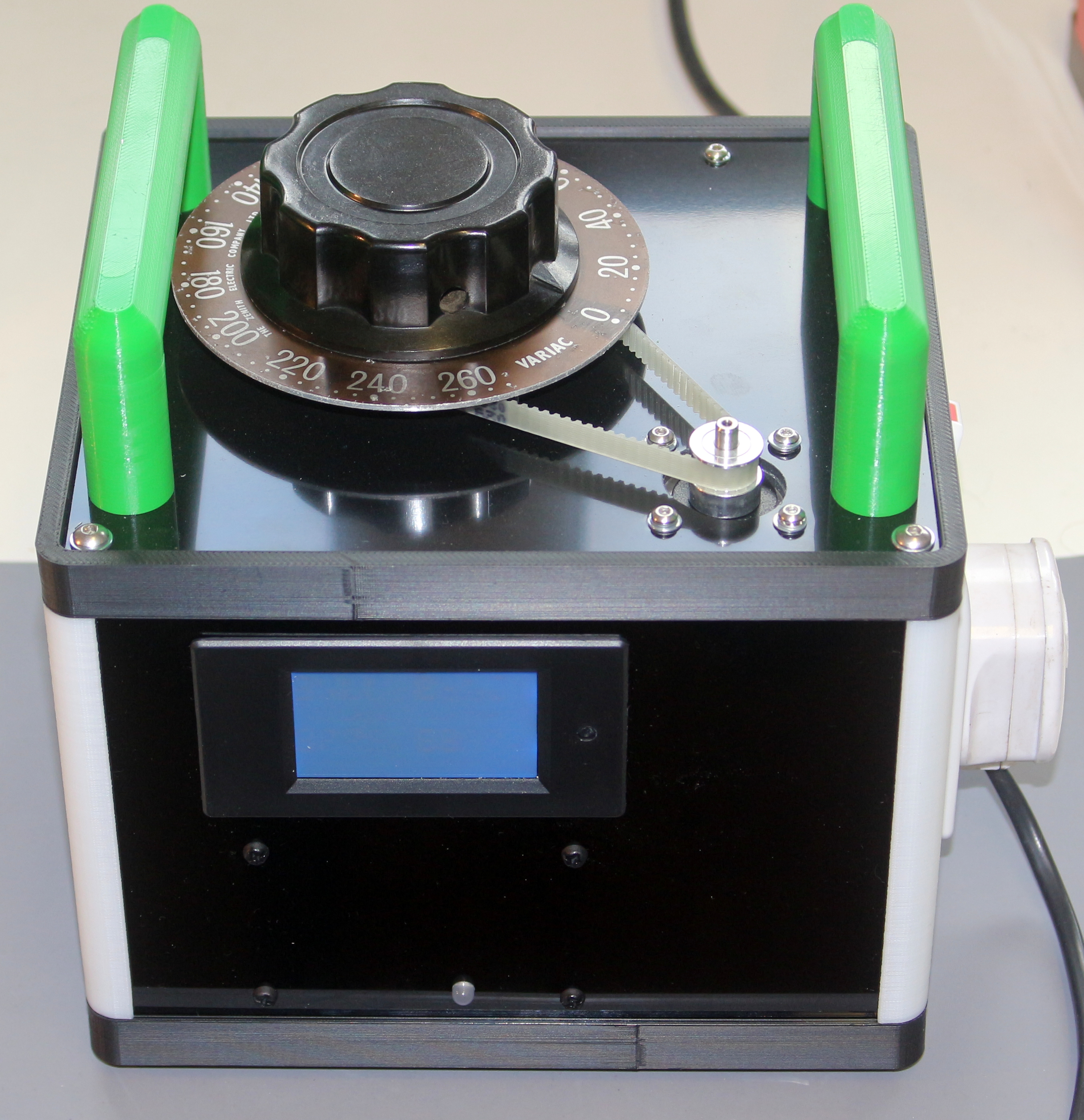
Since I had two faults to deal with I wondered if there was something systemic wrong with the board, such as the power supply. I powered it up on my bench using my 3D printed isolated variac supply that I use mainly for repairing switch mode PSUs, safely.
The power rails seemed fine. The isolated supply was about 12V, the non-isolated supply of the main board was 13.4V. I don't know if that was correct but most things are run from the regulated 3.3V supply derived from it and that was spot on.
I also couldn't find anything wrong with the opto board. All the optos seemed to be working and their data sheet advertises "Low CTR Degradation". I didn't know that was a thing but apparently the LEDs in optos slowly wear out and that is bad when they are used in the feedback loop of power supplies.
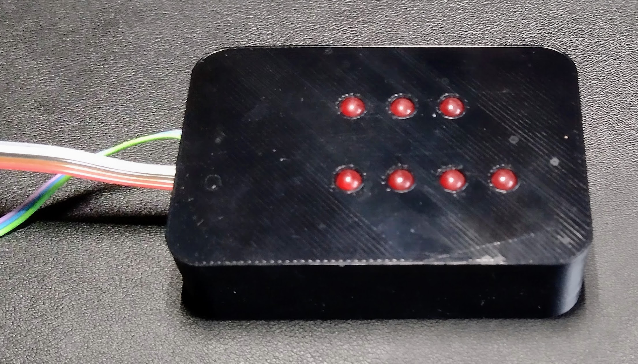
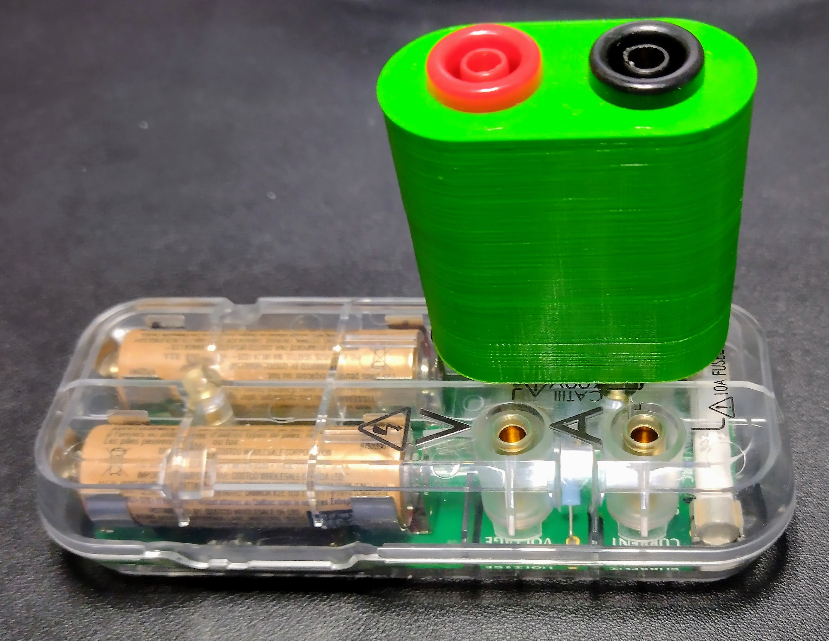
My attention moved to the relays. They looked fine and the soldering to the PCB was solid. It wasn't easy to test them on the bench because the board doesn't do anything without its button controller and all its I/O. I didn't want to put power on the relay coils to test them as it risked damaging the board, so I made a little 3D printed box with seven LEDs to display the state of the four transistors driving the relays and the three relay contacts.
I soldered it to the PCB using a ribbon cable that fed through a gap in the plastic case, so I could run the machine relatively safely.
I put the controller back in the machine, took out the lower basket and spray arm and put a thermocouple in the sump. I ran the quick wash cycle that only takes 45 minutes and heats to 45°C for its wash cycle. The thermocouple said it heated to 43C, which is close enough for me, and it ran the complete cycle with no errors. The LEDs worked as expected.
Thinking it might have just been a loose connector I filled the machine with dishes and ran the normal eco cycle that takes 3.5 hours. This time it ran the cycle cold and stopped with the EO2 error again, so back to square one.
I managed to find out how to get into a self test routine by holding the Pre-Rinse and Info buttons while powering it on. That displayed two recent errors which were the E02 and an aqua sensor calibration error. The aqua sensor measures how dirty the water is and you can select programs that vary the wash cycle accordingly. I don't think it is used by the quick wash or the eco programs we use.
After doing several steps the self test got stuck due to a comms error. I tried running it again but that caused a flood because it seemed to fill the machine that was already left full by the previous test not finishing. The water level overflowed the door hinge, went into a gutter which has a down pipe into the base of the machine. The water collected there and triggered a float switch that is a disk of expanded polystyrene under a microswitch. When the flood sensor is triggered all the machine will do is run its drain pump. Since that can't empty the base the only way to fix it is to bail out the base or wait for it to evaporate. I did the latter and decided to study the controller while I waited.
I noticed that an SOT transistor near to the thermistor inputs was a bit crooked, so I poked it with my fingernail and to my surprise it moved. It is the left most transistor here.
I desoldered one leg and it fell off in pieces. It had a hole through the middle like it had been blown up but tracing the circuit I found it was just switching a 150Ω resistor to ground. It looked like it was an LED driver for one of the optical sensors. I found a wiring diagram for a similar machine and it seems to be where the aqua sensor connects, so it must be an optical sensor and the LED is switched off to save power and sensor life. So that explained the aqua sensor error.
The SMT marking code seemed to indicate it was a Nexperia PDTC143ZT NPN "Digital" transistor, which has a pair of internal resistors connected to the base. I confirmed this by measuring the base resistance of another device on the board with the same markings. I had to order 50 from RS at about 25p each. It was tempting just to stick a MOSFET with the same footprint on as it would have worked but might have needed a pulldown resistor between source and gate. I can probably use the rest in other projects where I would normally use a MOSFET to avoid the need for two resistors.
The thermistor inputs just connect to two pullup resistors and then the MCU inputs. One is 8.2K and it measured spot on my UNI-T UT61E 22000 count DMM. The other is 4.7K and it measured nearly 1% low. The resistors looked special because they were green and bigger than others. I think they might be high stability / close tolerance so, as I was putting an order into RS anyway, I ordered a 0.1% 25PPM high stability resistor as well but had to buy 20 at 42p each. I didn't think it needed to be that accurate though because thermistors are usually only accurate to one percent at most. I have no idea how close the firmware expects the readings to track before it gives an error but I assumed it would allow a reasonable tolerance before giving an error, so I didn't expect it to fix the E02 errors.
As I wasn't really making any progress in diagnosing the two original errors I decided to bring in the big guns. I have a Mooshimeter Bluetooth enabled multimeter that can can log to an internal SDcard, so I thought that was ideal to log the thermistor voltages over a full wash cycle.
The only problem is it has only one auto ranging voltage channel. The resistance input can be used to measure voltages but only up to 1.2V, so I needed an external attenuator. I decided to 3D print one that would maintain the cat III safety rating. I was, after all, connecting to a controller that is not isolated from the mains.
I used the pins from a couple of 4mm banana jacks and 3D printed threads in the base to accept them at the standard 3/4" pitch used for multimeter input terminals. The input impedance is 10MΩ and there is a 10 turn pot to fine tune the ratio to 10:1. Strangly the Mooshimeter seems to have an unmeasurably high imput impedance on the Ohm socket when used as a voltmeter, so I didn't need to take that into account.
One problem I did have was bit-rot because I bought the meter in 2016, so of course it doesn't work properly with my latest Android phone. It wont stay connected long via Bluetooth BLE. I had to dig out my previous phone and that did work except emailing the log files from the app no longer works due to some permission problem. I had to find the uploaded file in the Files app and email it from there. It is crazy buying hardware that needs an app to function because it wont stay working for long unless it is actively maintained. Especially true for obscure test equipment because I only use each item occasionally. My home made IOT devices serve up a web page over Wifi, so they should stay working a lot longer because they work on any phone, tablet or computer without an app, and can be scripted with Python and curl.
My UT61E multimeter has an optically coupled serial interface, so I can connect it to my laptop to log readings from live equipment. I decided to use it to measure the 3.3V supply to see if that ever goes flaky. Again that has bit rotted because I bought it in 2015 and this is the first time I needed the serial link. The serial connection now needs a USB to serial converter because even my old laptop hasn't got real serial ports and I couldn't get the software to run on it. Not sure why, but it was pretty crap as far as I can remember. I managed to find a
Python script on Github that I could hack to do what I needed.
I couldn't get the serial interface to work until I took it apart and realized it needs RTS to be negated because it uses it for a negative supply rail. I rewired it to use RXD as that isn't used by the interface, so is always driven negative by TXD from the host.
To investigate the comms errors I eventually used three more instruments. I attached my Saleae 8 channel logic analyser to the optically isolated end of the serial bus. It connects to my laptop with a USB cable, so isn't isolated, but that is OK for the isolated end of the bus.
I also eventually added my Analog Discovery USB scope to the isolated serial bus as well. Both of these devices still worked well, without bit rot.
On the non isolated end of the serial bus I added my OpenScope WiFi oscilloscope, powered by a USB power bank to keep it isolated. Here it is in its 3D printed case:
I backed this on Kickstarter and it shipped in June 2017, so this was actually the newest piece of equipment but it has bit rotted the most and took me ages to get working. I think it was sold until 2020 and then suddenly
retired and no longer supported. Although the software is open source it hasn't been updated and the Android app seems to have disappeared from the Google Play Store, so only works on my old phone again. Worse than that, the web based interface served from Digilent's servers no longer works because modern browsers don't allow cross origin browsing.
When you open the web page served by the scope it redirects to
waveformslive.com and that tries to access the scope on your home network and that is now blocked by the browser. I tried a Chrome plugin that is supposed to get rid of CORS errors but I couldn't get it to work. You are supposed to be able to host the website from the OpenScope itself by putting it on its SDcard, but I couldn't get that to work either.
In the end I had to host it on my laptop using the Digilent Agent as a server and that did work. There is however a bug in the scope that causes it to regularly lose its WiFi connection and need to be reset when it is being rapidly triggered, but it will stay connected waiting for a trigger, so I did manage to use it.
So by the time I received the RS order, installed the new parts and got all this equipment attached and working by curing the bit rot and designing and printing the attenuator, the machine's flooded base had long dried out.
This is what it looked like before I had attached the Analog discovery. I soldered wire wrap wires to the PCBs and brought them out of the case to pin headers to allow probes to be connected. I also have a power monitor connected to the mains input so that I can see how much power the machine is using. It is only about 160mW when in standby mode, which is impressive. It takes about 4W when it is active but doing nothing. I.e. with the display active before the program is started. When the various motors are running it takes between 20 and 40W. The zeolite heater takes around 1.5kW and the water heater takes about 2.4kW.
So armed with all this equipment I ran a quick wash and it worked perfectly. I then ran an eco wash and it failed at the drying cycle with a comms error. Since I changed the thermistor pullup resistor and the transistor I have never seen the E02 error. I can't imagine the small error in value caused the problem because when I graph the resistances calculated from the voltages they only stick within 3% of the same value and when cold water is filling the sump, or the heaters are being switched on or off they can drift about 10% apart. This seems reasonable because heat travels relatively slowly through metals due to the heat capacity relative to the thermal conductivity. So even if the thermistors are mounted close together thermal transients may hit them at slightly different times.

This shows a quick wash with the voltages logged every 10 seconds and then used to calculate the resistances of the two thermistors. The program starts at the first dip on the left, which is where the water that has been standing in the tank on the side of the machine is released into the tub for the cold prewash. There is a small temperature increase at that point, so it must have been warmer than the sump water. Around the 100 mark the water starts to be heated to 45°C for the wash cycle by the main heater. I think the two peaks are where more cold water is added. The final slope on the right is where it heats the water to 85°C for the final rinse. It then finishes and the machine slowly cools down on the right.
The log of the 3.3V supply voltage every 100ms showed it was pretty stable:
So replacing the resistor somehow or other seemed to fix the EO2, and replacing the transistor fixed the aqua sensor error, but I consistently got the comms error during the drying cycle of the eco wash, when the machine is at it hottest. Thinking it might be temperature affecting the electronics, I ran the machine with the door controller and the main controller hanging out of it and it still failed in just the same way, so I then started to reverse engineer the serial protocol.
This is a typical packet captured by the logic analyser and decoded:
The data is sent at 9600 baud with a start bit, 8 data bits and one stop bit. The first byte (0x08 in this case) is the length of the packet's payload. The first nibble of the second byte is the destination device address. I came to realise it is a multi-master protocol and there are actually three devices. Address 1 is the main controller in the bottom of the machine, address 2 is the button controller in the top of the door that also controls a small LCD. Address 5 is a controller for the larger LCD on the front of the door. The bottom nibble of the second byte appears to be a packet type. Then comes the payload data, 8 bytes in this case, then a 2 byte CRC16 checksum. The 0x2A on the end is an acknowledgement sent from the receiving device. The top nibble is its address and the A seems to mean a positive acknowledge.
It wasn't obvious the last byte wasn't part of the packet at first. I thought it was an end of packet marker until I looked at the data on the OpenScope:
Here you can see the last byte's logic zeros go a bit lower than the preceding bytes. This is because the processor on the local side of the bus can drive it to zero but the device on the other side of the opto can only pull it low through a diode, so is a little higher. It was also a small differences in logic levels that made me realise there was a third processor in the door. This is actually a Microchip PIC24FJ256 that features a built in display controller and graphics accelerator.
The button controller sends packets to the main controller when you press buttons. The main controller seems to send regular status packets to the button controller and that forwards the status information to the display controller to update the big display. For example I could see a value in the payload that corresponded to minutes remaining in binary and that is shown on the main display during a wash cycle.
I don't think the main controller ever talks to the display controller directly. I am not sure how bus arbitration is done because I never saw a collision, but it seems possible if you hit a button just as a status message is due both the button controller and the main controller could start a packet simultaneously. They can both see their own data on the bus, so if there was a clash they could detect it and retry like Ethernet. Or maybe the button controller records when it got the last status message and knows when the next one is due.
Using the logic analyser and the two scopes plus a multimeter looking at the supply to the optos I couldn't find anything wrong with the serial comms. Even when it was displaying comms error all three devices were still talking to each other and being acknowledged. The packets were well formed at the transport layer and had the correct CRCs. There was no obvious way to know what all the packets mean at the application layer but after doing all this reverse engineering and monitoring I decided the communication error was probably a red herring and I needed to look elsewhere. My theory is the main controller goes into an error state and starts sending messages that the button controller doesn't understand, so it reports a communication error.
The communication error now always happened at the same point in the eco cycle, 40 minutes from the end where it had just done the hot rinse and drained the water. It waits a few minutes doing nothing and then turns the blower on. That is the point it fails. I knew there wasn't a problem with the blower motor because that is used earlier in the cycle to dry the zeolite with the heater on. At this failure point it blows hot steamy water over the heating element while it is switched off. When the machine cools down a bit the comms error clears. So if I had run it overnight, like I normally do, the only noticeable effect hours afterwards would be the dishes would not be quite as dry as normal.
When I was looking at the board near the faulty transistor the nearest chip is a SEN013, which is described as a "Zero loss high voltage sense signal disconnect IC". Note that ,although the 3 channel version of the chip is fitted, only two channels are used, so the SEN012 could have been fitted.
I had also noted that the LED that was monitoring the output of the live relay glows dimly even when the relay is off, so I decided to investigate the relay mains circuitry. This is what I found:
The SEN13 is used to monitor the state of the heaters. When all the relays are off then live is fed to the heaters via 220K and monitored by an analogue input of the MCU and the neutrals coming back from the heaters are summed and then monitored by the second channel of the SEN13. So the MCU can detect relays being open or shorted, heaters being open or leaking to ground. The SEN13 avoids wasting any power when the machine is in standby by disconnecting the sense lines. There is also a special chip that disconnects the X2 cap discharge resistor when the mains is on, so every measure is taken to reduce the power consumption.
So now I finally had an idea of what was going wrong. I monitored the sense inputs to the MCU with my isolated meters and found that the voltages dropped as the machine got hot and steamy. Suspecting the zeolite heater was leaking I measured its resistance to earth with a multimeter and still got an open circuit but when I reversed the probes my meter freaked out on the Ohms range. The heater was acting like a battery generating a few hundred mV. Lesson learned, always check for earth leakage in both directions! I still might not have not found the fault at the beginning because it was only leaky enough to cause a fault detection at the start of the drying cycle when it was hot and damp.
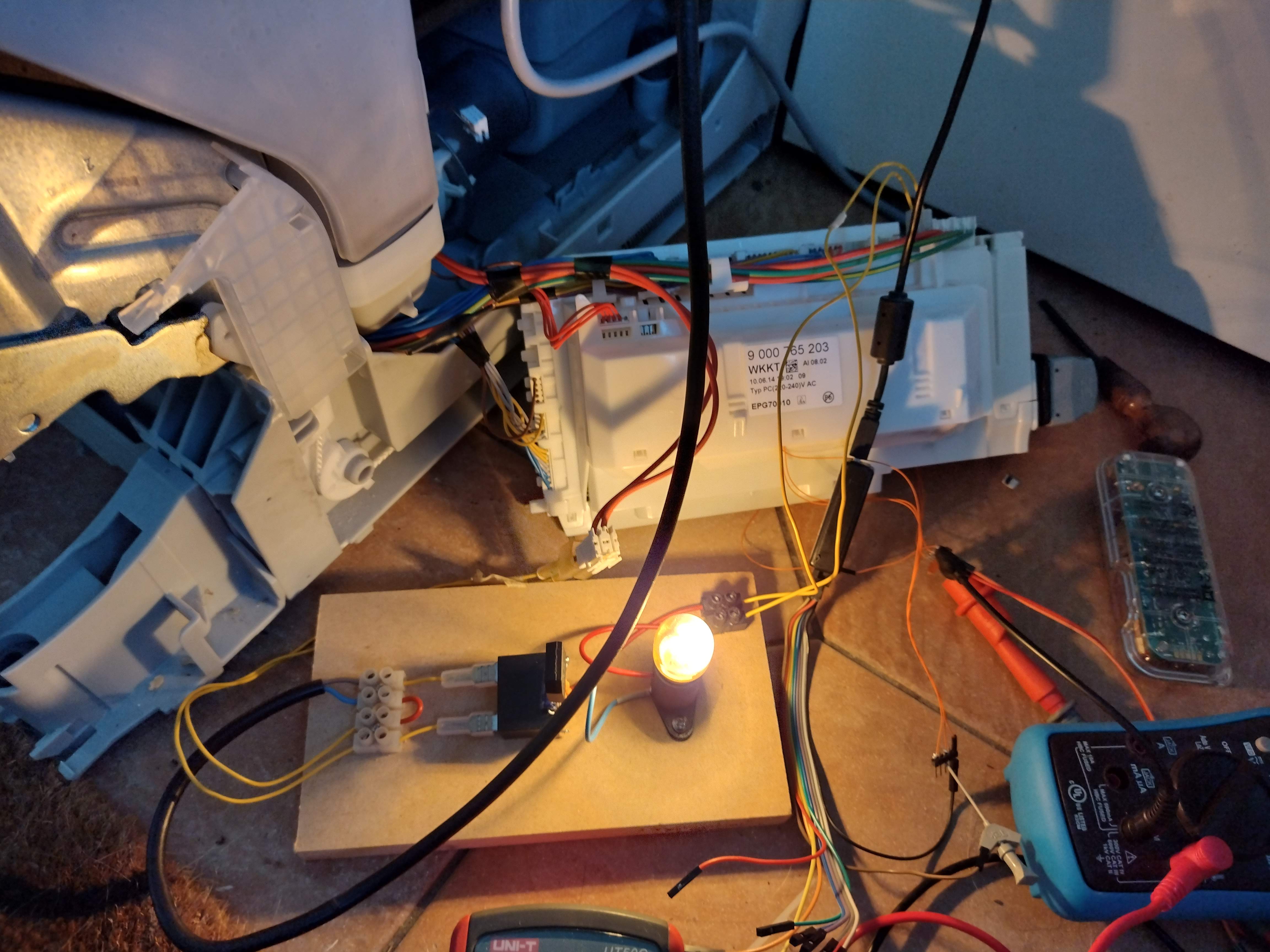
To test that my theory was correct I replaced the heater with a small incandescent bulb to fool the control unit it had a non-leaky heater. I placed a bridge rectifier and a relay in series with the bulb and used the relay contacts to drive the real heater directly from the mains via a second wall socket. The bulb had a small Edison screw base that I didn't have a socket for, so I had to 3D print one. Here is my lashup:
And here it is connected to the machine while it was heating the zeolite:
The machine was able to complete the eco cycle without a communication error, so I had proved my diagnosis correct after about 3 months of testing, reverse engineering and head scratching. It was driving me mad. My wife and friends said I should scrap it and buy a new one but after I had invested so much effort I felt I had to press on. It was only 2 days before we went on holiday again for a few weeks, so it as good to solve it before we went after the mandatory 90 days at home.
On return it was tempting to just minaturise the bodge and make it permanent because the zeolite heater is very difficult to access. When you blow steam into a bare heating element connected to mains live I don't think it is a surprise that you might get some leakage and I don't think it really causes a problem when the heater is enclosed in a steel tube that is grounded and the heater is already dissipating 1.5kW and sinks about 6A.
Eventually I plucked up the courage to attempt to remove the heater and see if it could be fixed by cleaning it.
The heater should look like this:
It just presses into the inlet tube of the zeolite tank and is sealed by the top o-ring. The peg on the side ensures the correct orientation.
But then it is held in place by the blower fan, which seals to the lower o-ring and has three barbed prongs that lock into slots in the metal flange of the tank.
The blower needs to descend to separate from the ventilation duct, so I figured I would need to remove the base of the machine. How to do that was not at all apparent. Older machines just have four screws to undo but all I could see were two bent tabs at the back of the machine. I couldn't see how the front was fixed. Fortunately I found
this video that showed how to remove the base of the same generation machine. It wasn't one with a zeolite heater but the basic construction was the same.
I would never have worked it out myself because there are three hidden plastic tabs that need to be released. To get to two of them you have to remove two covers over the door counterbalance spring cords, remove the cords and then remove the guides for the cords, the tabs are underneath those. Who would have guessed that?
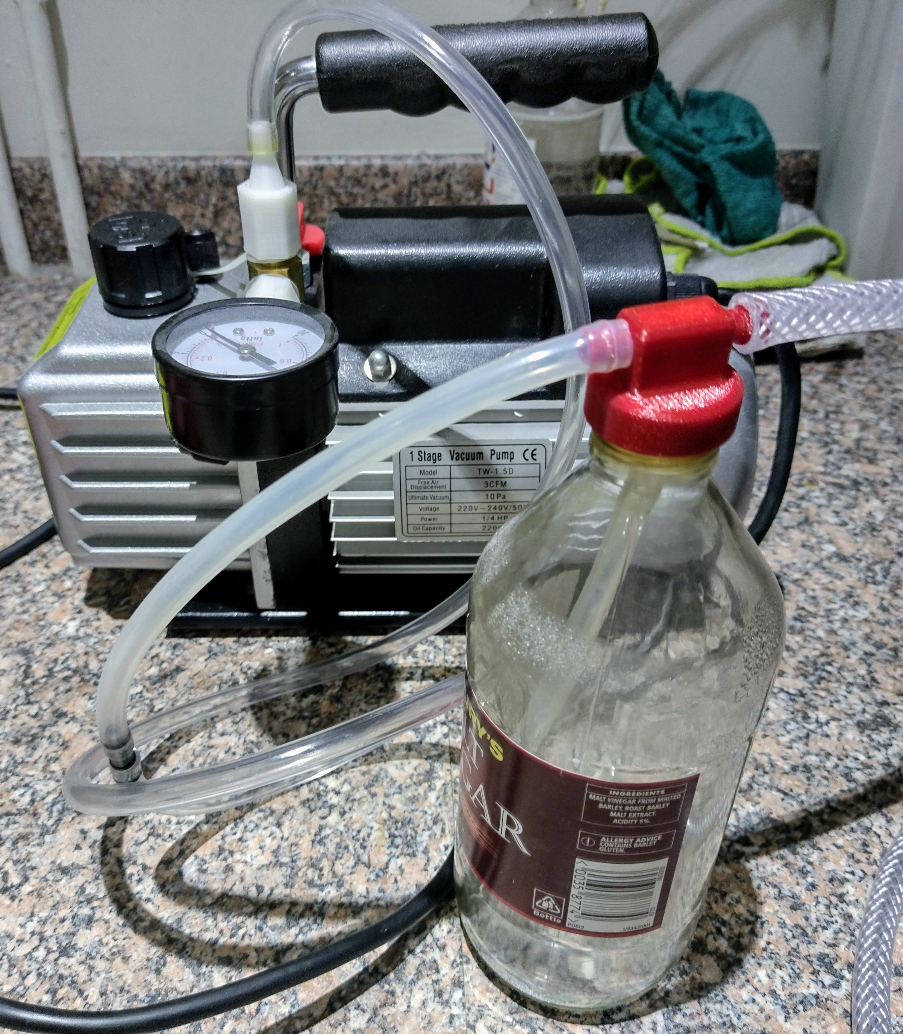
You also need to turn the machine upside down, so you need to empty the sump. I first tried to use a small water pump I bought to make a laser cutter but it wasn't self priming, so that was a fail. Next I decided to use my vacuum pump but I needed to separate the dirty water from the air to stop it entering the pump.
I found this
air assist pop bottle pressure filter on Thingiverse that screws onto a standard bottle thread and connects two pipes and allows a third one inside, so the water goes to the bottom while air is drawn from the top.
I found a PET pop bottle was no use for vacuum, and neither was a thicker HDPE bottle used for acetone, as they just collapse. So I ended up with a glass vinegar bottle and that worked well to empty the sump. I think I will do that each time we go on holiday from now on.
So that was the final bit of 3D printing for this project.
I managed to remove the base to get to the pump and with great difficulty remove the three barbed prongs that requires three hands and three pairs of pliers. When I removed the heater it left its glass tube behind because the inside of the tank was thick with rust that jammed it solid. I broke the glass removing it and then I had to Dremel out the rust in order to make room for a replacement heater.
The replacement was £129.40 including next day delivery from Bosch. Here is the new one next the old naked one:
The corroded electrode encased in the white ceramic tube in the foreground sits at the bottom of the glass tube when it is horizontal and is there to detect water. It connects to the control unit via a brown wire that has a mystery inline component encased in resin and tape. It measures as a 1nF capacitor and must detect AC leakage from the element if it gets submerged.
After breaking the glass it was hard to determine what was causing the leakage but there was a lot of black charcoaled strips of material amongst the elements that I think was the remains of the silicone glue that joins the glass to the base. Here are some small bits of it:
Perhaps it became detached and the fan blew it into the elements and somehow bridged to the rust.
This is a view into the tank after I had Dremeled most of the rust out of the inlet tube. Notice how corroded the bottom of the tank is (at the top of this view):
It was a total mess of corrosion and I think that it is a design fault to use galvanised steel for something that has hot water vapour passing through it regularly. My understanding is hot water and steam are far more corrosive than cold water and galvanised steel doesn't even last long outside. I don't know why they didn't use stainless like the rest of the tub.
A replacement zeolite tank is £159.41 so I didn't feel like replacing it, but I don't know how long it will be before it rusts all the way through, especially as there is now bare steel where I Dremeled it. If it did leak it would only be water vapour that would escape, it shouldn't flood as the inlet and outlet are above the high water line.
Putting the base back on the machine is difficult because it is obviously designed to be assembled the other way up at the factory, but that would need a hoist. I tried to improvise one with two stepladders, a plank, four luggage straps and a ratchet strap but that was a fail.
The difficulty putting the base on upside down is that there is a big weight at the back to stop the machine tipping forward that isn't fastened to anything, it just sits in the base. On the zeolite machine there is also a metal heat shield under the zeolite tank that just sits in the base as well. It falls out when the base is removed upside down. So again you need lots of hands to hold them in place while the base is clipped back on. They are then trapped in place.
Then I had to find all the parts spread around the house for four months and remember where they all went. Amazingly there was nothing left over, not even the usual screw, but there aren't that many in this machine. Lots of plastic parts just clip together. Obviously designed for cheap and easy assembly, not easy repair.
I ran the self test and it went through something like 75 steps in an hour and a half and seemed to pass them all. I wish I had put crockery in because it was twice as long as a quick wash!
So the machine is up and running again but having three different, unrelated faults occur at the same time is weird. The broken transistor seems to have been a manufacturing fault. Assuming it worked when new, it must have been soldered on crooked, in a way that left it under great stress, and then it later cracked.
The earth leakage problem was misreported as a comms error and that wasted so much of my time. And the E02 error fixed by changing a resistor value by a fraction of a percent makes no sense, so perhaps it will come back to bite me. Or perhaps it was another manifestation of the earth leakage problem because the first heating in the eco cycle uses the zeolite heater. That would explain why the quick wash cycle tended to work because that doesn't use the zeolite heater at all. Better error codes and available schematics and wiring diagrams would have made the job so much easier.