The
RepRap machine uses a network of
Microchip PICs plus a comms board to control the axes and the extruder(s). The controller boards are multi-purpose so this gives a flexible scheme for experimenting and extending the machine. This topology does not make so much sense for HydraRaptor because I have invested in a set of professional quality axes which I hope to be using in a stable configuration for a long time. Using three controller boards plus a comms board to drive these is a bit over the top.
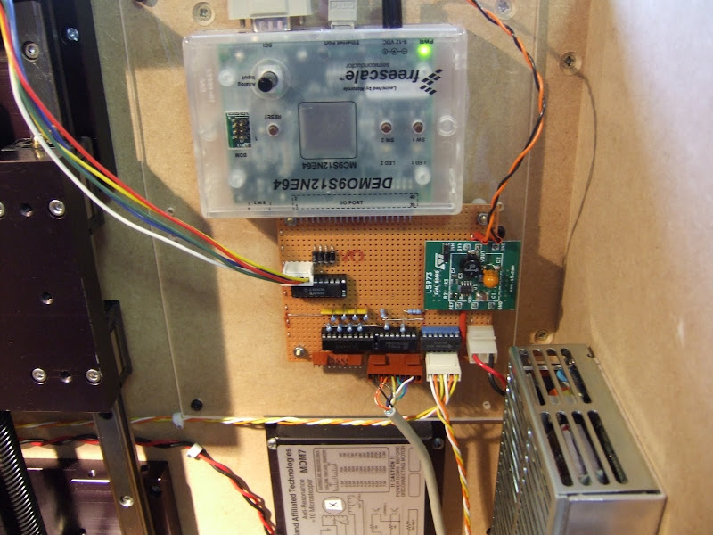
Instead I have chosen to use a demo board that I had lying around to control all three axes. This is a
DEMO9S12NE64 from
Freescale Semiconductor. It has an on-chip Ethernet controller and a good array of analog and digital I/O ports plus serial ports, timers, etc. It comes with a free TCP/IP stack and a CodeWarrior IDE, C compiler and debugger.

I bought this a couple of years ago from
Digikey to acquaint myself with Ethernet and TCP/IP but had not really done anything with it. Strangely, although the chip has masses of I/O, only a subset of this is available at the connector and some of these lines are also connected to the on-board switches and LEDs. Annoyingly the C compiler has a 12K code limit but that should not be a problem for this project. The IDE and debugger are not the best I have used and I have seen the compiler produce some terrible code. There is no excuse for this as the instruction set of the 9S12 is fully featured and well suited to C, unlike say the PICs. Sadly most C compilers I see these days produce worse code than one I used 20 years ago.
It comes with a preloaded monitor program which allows code to be loaded into on-chip flash via a serial port and then debugged at the source or register level with breakpoints and single stepping, etc. All in all the dev kit is not too bad, certainly nicer than the Microchip stuff.
I will use Ethernet to link my machine to the PC as that gives me complete freedom where I locate it. There is enough I/O to drive an extruder as well as the axes. I may well do that initially, but eventually I will use one of its serial ports to drive a network of head controllers.
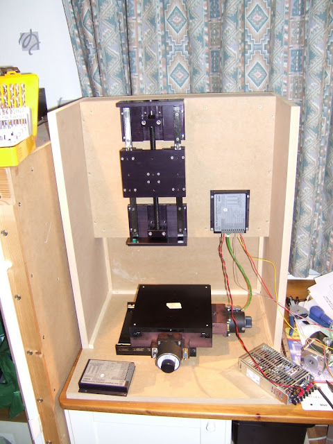
One snag of using the demo board is that it is 3.3V volt logic. My XY table uses 5V logic so I had to do some level translation and that is most of what the veroboard underneath is about. The outgoing signals to the opto inputs of the stepper controllers are driven by a 7407 open collector buffer. The proper way to handle the incoming signals would be to use a level translating buffer chip but I didn't have any to hand and I suspect they are not available in leaded packages as most 3.3V stuff is surface mount. Instead I buffered them with a 74LS244 and then used potential dividers to drop the voltage. If I had not buffered first I would have reduced the noise immunity in the long leads around the machine which would not be good. This way it is only the noise immunity across the board that is slightly compromised.
Other things on the board are the z-axis driver and a 2A switching regulator which steps down the 24V to 5V to drive the level changing logic. This is actually an
L5973 evaluation board from
ST. Doing this with a linear reg would waste a lot of power and need a big heat sink. The
DEMO9S12NE64 comes with its own 6V mains PSU but I found it works fine fed from 5V as well.
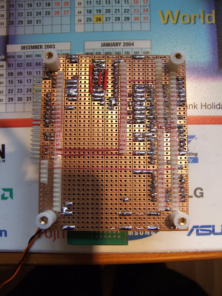
I wired the board using the
Verowire system, see
en.wikipedia.org/wiki/Wiring_pencil.

This is quite a quick way to produce high density prototype boards but it is a bit fiddly and requires a lot of concentration. It is not easy to make changes afterwards either.
In summary I was able to cobble together the control system from bits I already had.