Erik asked me for details of how I do the rafts so here are my thoughts.
I am not totally happy with the way they are currently and keep fiddling about with them. At the moment they hold well and give a good flat surface on the bottom of the object, but they can be difficult to remove. I use a blunt penknife to remove them.
I use the long blade to remove the raft from the bed and the object. The smaller blade is handy for clearing out strings from internal areas.
It needs to be not too sharp otherwise it tends to cut into the object, or the bed, rather than prizing them apart, or scraping off strings.
I have developed a thick callous on my thumb while making the Darwin parts, and I frequently stab myself, another reason for not having it too sharp!
I think most people use more sparse rafts than I do. They will be easier to remove, but I find that gives a ribbed base on the object.
My rafts are orthogonal to the axes and the infill is at 45°. I find that convenient because you can tell where the raft ends and the object begins.
The bed I use for ABS is, I think, Foamex PVC foam board. It is a solid dense foam 3mm thick, not the type that is soft foam laminated with paper. I glue it to a piece of wooden floor laminate with Evostick contact glue. Now that Evostick has gone solvent free / water based I find it takes much longer to dry than it states on the tin. Blowing it with a gentle breeze from a fan makes it dry much faster.
Even when it is glued down, I find the warping force is strong enough to lift the edges, so I have a frame around the edge that is screwed down. The foam board is reusable over and over again. I only have to replace it when I have had an accident that makes the raft impossible to remove (head too low, or temperature too high).
Other people have reported good results with Acrylic sheets and of course an ABS sheet will work. I have yet to try these. For HDPE I use a PE-LLD chopping board from Ikea that is 10mm thick.
I find that I need at least three raft layers. I.e. each of the three layers has a definite function.
The first layer of the raft has to stick well to the bed but still be peelable. It also has to be thick enough to cope with bumps and troughs that develop on the bed with use and slight errors in the z-calibration.
The filament diameter I use for the base layer is twice the nozzle diameter or 0.8mm, whichever is the biggest. The height of the head is 0.7 times that. The pitch of the zigzag is 3 times the diameter. The head is relatively low, so that it gives a wide filament pressed against the bed. It is widely spaced so that when the bed has a bump it can spread further without merging. It is extruded at the maximum rate that the extruder will do, which works out at only 4mm/s with 1mm filament through a 0.5mm nozzle. The temperature is 225°C for ABS and 215°C for HDPE. The other layers of the raft are extruded at 240°C to bond strongly to the layer below.
The middle layer's function is to give the raft some strength and bridge the ridges created by the bottom layer. The filament diameter is 1.5 times the nozzle aperture. The height of the nozzle above the layer below is again 0.7 times the nozzle. The pitch is 1.2 times the diameter, so that gives closely packed threads that tend to merge.
The top layer aims to present a flat platform to the object but still be discrete threads so they can be picked off one by one. The diameter is the same as the nozzle and the height is 0.8 times that. The pitch is 1.8 times the diameter.
The raft is cooled back to room temperature with a fan before the object is placed on it. The first layer outline of the object is done at half the normal speed (8mm/s for ABS, 4mm/s for HDPE) and at a temperature of 215°C for ABS and 230°C for HDPE. The first layer infill is done at full speed and at 195°C for ABS and 205°C for HDPE. The rest of the object is 240°C.
One annoying thing is that when I peel the raft most of the top layer is left stuck to the object not the middle layer. This is despite the fact that it was bonded to the middle layer at a high temperature, and to the object with a low temperature. I think the reason is that the contact area is 100% against the bottom of the object, but the top of the middle layer is quite wavy so has less contact area. I think adding another dense layer between the middle and the top will fix that, but waste more time and plastic. It is on my very long list of things to try.
As Erik suggested, small objects do not need to be bonded as strongly to the raft as large objects. Something else I mean to try is some logic like this: -
If the length or the width is > 30mm and the height > 5mm then use a strong raft else a weaker one.
When I was printing 24/7 for about 5 years I never had a problem with filament absorbing moisture because the heat from the machines kept the rooms they were in hot and dry and the filament was stored in the same rooms as the printers. In fact in winter it was so dry I had to buy a long conductive ESD mat that runs the length of my workshop and wear ESD ankle straps to prevent getting sparks off everything I touched.
Since I retired I print more sporadically and tend to go away in winter and leave the heating at only 12°C. I still didn't have a problem with the white ABS that I got from Germany for kit production. It was unusual in that its natural colour was white instead of cream and it didn't smell much while printing. I used to find that I might get one or two bubbles in the skirt round the object but after that the rest of the print was fine. It appeared that filament sitting in the extruder from the last print would absorb some moisture over time but the rest on the spool that hadn't been melted did not, no matter how long it was left.
I also got some black ABS from the same German company and that is totally different. It bubbles very badly and needs to be dried. It also smells like ABS when it is printed. I never got good results from printing it, so I put off using it for years until I ran out of white. I then decided to tackle the moisture problem. Inspired by RichRap's heated dry box, I designed a parametric heated dry box that I could tailor to fit any size spool.
When I made the Dibond version of Mendel90 I noticed the dummy load resistors for the ATX PSU ran a lot cooler than they did on the MDF version. I came to realise that Dibond makes quite a good heat spreader even though the aluminium layers are only 0.3mm thick.
I also had lots of 47 Ω 50W TO220 resistors from various heated bed iterations that didn't go too well. Since this doesn't need to get very hot or need much power I thought it would be a good way to use them up.
I have a parametric box in NopSCADlib that is made from Dibond panels and printed brackets that can be scaled to any size that fits my CNC mill, so it was easy to wrap that around my large 2.4kg spools and add 12 resistors along three sides. The spool runs on 608 ball bearings between penny washers, there is a thermistor to monitor the temperature and a small fan to stir the air around.
I ran the resistors in series from half rectified mains to give a total wattage of 51W. I earthed all the panels and covered all the connections with heat shrink sleeving but it wouldn't pass any safety standards as the wiring isn't double insulated. Safe enough for me though as I don't need to put my hands inside it but I wouldn't recommend it.
For my smaller 1kg spools I use 9 resistors and wire them in parallel for 12V operation. That gives 28W, which is enough for the reduced surface area and much safer.
To reduce the energy consumption I obviously needed to insulate the outside of the box, so I suspended it inside another slightly larger box and filled the gap with cotton wool. It is a lot nicer to work with than fiberglass or rockwool and quite cheap in the quantities needed. It is also just the right thickness to fill the gap, which is dictated by the corner fixing blocks. Even without the cotton wool the air gap gave quite good insulation. The only connection between the inner and outer cases is a few printed standoffs and the wires and filament exit guide.
It is completed by a hinged double door made of acrylic sheets with a hygrometer and thermometer module in the inner door. An arduino Leonardo with an LCD, some buttons and a couple of MOSFETs controls the temperature and the fan and keeps a record of the heater duty cycle. Again parts I had to use up.
So basically I created a 3D printed fan oven!
The base of the outer box is extended, so it bridges the frame stays of my Mendel90s after removing the spool holders. Four fixing blocks stop it sliding off but are only screwed to the base, not the printer., so it can be lifted off and they then act as feet.
The mains version is controlled by a stand alone Arduino thermostat I had previously built to control a beer fridge. Another reason the first version was mains operated.
I have parts to make a third one the same as the second, after that I will probably make it headless with an ESP8266 and an I2C temperature and humidity sensor.
To dry the ABS filament I set the temperature to 80°C for a few hours and then left it at 50°C, even when the printer is not in use. The relative humidity in the box drops to about 19%. In the room it is about 60%. When I was printing 24/7 it used to be well below 50%.
As well as stopping bubbles it improves surface finish making it more glossy, makes bridges pull tighter, completely stops nozzle ooze at the end of a print and even reduces the ABS smell while printing to almost nothing.
At the end of a print I retract an extra 1mm and turn off the heater before moving Z back to the top. Without the dryer I used to get 10 to 20mm ooze out of the nozzle as the extruder cooled down. I had always assumed this was due to gravity but it is in fact due to moisture turning to steam pushing the filament out. When it is dry the surface tension must be sufficient to stop any flow due to gravity.
I was used to snapping off the ooze before I start a build, it had become an unconscious action, but now there is nothing to remove. It will be a big advantage when I make a multi material machine as there should be no ooze from the idle extruders while another is being used.
The reduction in smell was a complete surprise. Before I dried the black ABS it seemed to smoke as it came out of the nozzle. I now realise that was water vapour and it must carry off some volatile products. It now hardly smells at all when printing but if I stick my nose in the dryer it does smell of hot plastic, even though it is only at 50°C. I guess the moisture it has driven off carries some VOCs with it.
About a year ago I got some wood coloured ABS in the UK which was even more affected by moisture than the black, so that is when I built the second smaller dry box, around October. After drying it printed very well. I made this replacement handle for a curtain puller with it.
After switching the dry boxes off when we went away for the winter I turned them on again in March and they have been on ever since. I last printed with the brown plastic at the end of May and it was fine but when I tried to use it yesterday it has gone super brittle. The coil has a very strong heat set, something I don't like about 3mm filament on 1kg spools, and bending it straight now causes it to snap.
I was trying to use it on my original MDF Mendel90 that is now encased in a box with a chamber heater. The filament feeds from the top of the box rather than through a PTFE tube that runs all the way to the extruder. The part that was outside of the dry box for about seven weeks was still ductile but had moisture in it. When I pulled the dry part from the box through it just snaped, so I can no longer print it on that machine.
It does still seem to work on my Dibond machines that do have the PTFE tube all the way to the extruder. That keeps some of the coil's curve and doesn't require it to be fully straightened.
And the printed objects don't seem to be brittle at all. I haven't done any proper strength tests but a quick test bending a small 100% filled block with pliers it bent and got white bruises like ABS normally does.
So keeping brown ABS at 50°C for a few months seems to completely denature it but a melt cycle seems to restore it. I have heard of PLA going brittle on the spool but nobody seems to know for sure what causes it. PLA is also somewhat brittle but ABS isn't at all. Presumably the long polymer chains must get shorter somehow and then reform when melted. I am not sure if the temperature is the problem or if it is too dry. I have read there is an optimum moisture level for processing plastic at, rather than as dry as possible, not sure why.
The black ABS hasn't gone brittle yet and it has been in its heated box for longer.
My prototype MDF Mendel90 runs with a chamber temperature of 45C and I have noticed that the printed parts it is made of seem to become brittle over time. The extruder runs a lot hotter of course and the Wade's block tends to crumble after a few years and needs to be replaced regularly. They last a lot longer on my unboxed machines.
I also think ABS shrinks over time, even at room temperature. I made a test print with some holes in it a four years ago when I was having an interesting discussion about Polyholes with Giles Bathgate. I tested it with plug gauges but as I didn't have a case for them I left them standing in it on a shelf near a north facing window. When I went to use them for my Horiholes test I found they were stuck in it much tighter than I remembered and the plastic has yellowed slightly.
I made a case for them with a screw top using my thread utility in NopSCADlib, printed in the black ABS.
So now I have dropped the temperature of my dry boxes to 30°C as surely that won't degrade the plastic much more than in a hot room without sunlight. That vastly reduces the power consumption of course. 50°C needed about 50% duty cycle but 30°C is only 4%, only a shade over one Watt. The hygrometers are still reading 19% after a day at the lower temperature. I find that odd because, for a given air water content, reported relative humidity should increase as temperature falls.
So I think I will try initially drying new plastic at 80°C overnight and then reducing to 30°C for long term storage from now on and see how that goes. A good measure of whether it is dry enough is the complete lack of ooze at the end of the build.
Since my last post there have been many expressions of sadness in the comments here and here. I'd be lucky to get so much mourning at my funeral I think! Yes it may be sad for potential customers that missed out, but not for us. Fortunately we are at a stage in life where time is more important than money to us. It does feel a bit weird though as the house is now silent after having three or four machines printing solidly for about five years.
The harsh reality is we always planned to stop selling kits before demand dried up completely because otherwise we would be left with unsold stock. In order to to get volume discounts and cover long lead times we needed to carry around £12,000 - 15,000 of stock.
As we didn't hire premises or staff, and had enough capital to cover cash flow, the only business risk we had was being left with stock. It was very hard to predict future demand because it fluctuates wildly
with currency changes and, with a new 3D printer coming out nearly every
day, there is a risk sales could suddenly dry up if a better cheaper kit
emerged. For example, a £40 Prusa I3 from China with 2 rolls of filament and LCD, bargain!
In the end the issue with Dibond made the tricky decision of when to stop for us. This happened a few months ago and we synchronised most of our stock to all run out together.
Yes we could have used other sheet materials, solid aluminium and steel were suggested. However, these are more expensive to buy and machine, much heavier and therefore more costly to ship. Although they are a bit stiffer there is no real advantage to the frame being stiffer because the forces due to accelerating the axes is along the plane of the sheets, where almost any sheet is very stiff indeed. As long as the machine sits on a solid work surface it doesn't flex at all when printing, unlike some of the triangular prism machines.
The good thing about an Open Source product is that the design and instructions will always be available, so people can still self source, or another company could pick up the baton. We will always be able to supply printed parts and, fastener kits, wire and sleeving, hobbed bolts and the extruder PCB. See the RepRap forum for prices. Everything else can be self sourced.
I decided to make a tool height sensor as a high priority because finding the Z = 0 setting manually is time consuming and risks breaking expensive milling / drill bits. I got my design inspiration from The "One Penny" Touch Probe. I basically turned it upside down. My plan was to have a spring loaded disk pressing upwards against three contacts. Any movement of the disk downwards must break at least one connection. Note that the circuit in the aforementioned article is a little bit more complicated than it needs to be. Rather than use a three input OR gate you can just connect one of the contacts to ground and use a two input OR gate. That also dispenses with a connection to the disk.
Things went well to start with. I milled a ring with three flats on it out of 6mm Perspex. I drilled into the flats and inserted three gold plated pins extracted from a 0.1" header.
I then milled a base which bolts into one corner of the tray on top of my XY table. It has a circular recess to locate the base of the contact ring and a blind hole to house the spring. The corners are all radiused.
The small screw hole in both pieces was drilled manually with a small drill press, the rest was all done by Python script driving HydraRaptor with a 1/8 inch end mill. Here is a video of the ring being made, the flats were added by a third pass :-
The perspex milling went remarkably well at 10 mm per second feed rate, 0.1mm cut. I glued the sheet down onto the sacrificial base (floor laminate) using plasti-kote stencil mount. This worked well but I had to leave it 24 hours to dry because it was pretty much sealed between the two sheets. I removed it from the workpiece afterwards with Stain Slayer tar and grease remover.
The only slight defect was that the parts are slightly undersized for most of their height, but a bit bigger at the bottom. At first I thought that the tool wasn't plunging deep enough into the base material. I tried increasing that with no effect, so the explanation I came up with is that the tool gets a bit clogged with perspex and that rubs against the work piece making it slightly undersized and gives it a polished appearance higher up the edge.
Flushed with success, I thought making a conductive disk would be a doddle but it turned out much harder than I thought. My first idea was to mill a 9.5 mm disk out of PCB material. I stuck that down with stencil mount but I only left it to dry a few hours. It came lose while milling, creating an egg shape.
My second idea was to turn down a cupro-nickel disk on my watchmaker's lathe. I can't say where this disk came from but I can say that it cost exactly 5p. My plan was to hold it by its outside edge in a chuck and plunge a tool into the face to get the correct diameter. After an evening of trying every tool I had and shaking the lathe apart I realised that is not an operation you can do on a lathe. Normally you cut across a face or along the length of the piece. In that case only the leading edge of the tool is actually removing metal. If you try to plunge a tool into the face of the workpiece the whole of the tool width is trying to cut. It just digs in and stalls the lathe. Perhaps a very thin tool might work but I don't have one. The only way to reduce the diameter with the lathe is to turn it from the outside but then there is nothing to hold it by.
My third idea was to turn down a bit of 10mm brass bar and then cut the end off to make a thin disk. This worked at the second attempt, after I had improved my lathe skills a bit. Here are the three rejects :-
And here is the one that worked :-
I made a 5mm stalk on the back to locate the spring :-
And here is the assembled sensor :-
To my amazement when I metered it out there was no connection between the contacts. How could brass pressed against gold not make contact? After close inspection I realised that the disk was resting on small Perspex burrs where I had drilled the holes for the pins. I removed the pins and scraped off the burr with a pen knife and that fixed it.
Tomorrow I will wire it up and see how it performs. The only thing that worries me is that the brass might tarnish with time. At least it will fail safe if it does. I have a small gold watch case that I can cut a disk from if need be.
The magnetic steel and polyimide tape bed works very well for manual operation but I am pursuing the vacuum bed idea for fully automated production. I went through a few designs in my head before actually making anything.
The first idea was to drill an array of holes through an aluminium plate and connect them on the back by milling a network of channels. I would close the top of the channels with some Kapton tape. The problem with that idea was there was then nowhere to mount the heating resistors unless it was on top of the Kapton sealing tape, which didn't seem ideal. My solution to that was to mill a channel into the edge of the plate and wind a coil of nichrome all the way round it. That was my plan until I realised there would then be nowhere to attach the vacuum hose.
A solution might be to use a Kapton or silicone stick-on heater and use it to seal the channels in the underside.
What I actually did was to mill a grid of very fine channels into the top surface allowing me to attach the vacuum hose to the side edge and drill a small hole down to meet it, leaving the bottom free for the resistors and thermocouple.
The channels are about 0.5mm wide and 0.5mm deep on a 5mm grid. I milled them with a 0.3mm conical bit that I bought for milling PCBs.
I used a feed rate of 2mm/s and 0.1mm cut depth per pass. My MiniCraft drill runs at about 20,000 rpm. The results were not very good. I have only ever milled plastic before with HydraRaptor. It struggled cutting aluminium such that the shaft of the drill was being displaced in the direction of the bed travel. It raised a burr about as high as the channel is deep. My friendly local milling consultant told me afterwards that aluminium does not like lots of flutes. He recommended a D-shaped cutter with a single cutting edge and a higher spindle speed.
I sanded the surface flat with 240, 600, 800, 1200 and 1800 grade wet-and-dry sandpaper and then polished it with metal polish. I did this to get as good a seal as possible with whatever was placed on top.
I attached some polythene pipe using an M5 copper welding nozzle screwed into a tapped hole in the side of the plate. I use a tapered tap so that the thread would bind to form a seal. I used Fernox LS-X jointing compound to make sure it was airtight. I think it is silicone, so should handle the temperature.
I was hoping to get a perfectly air tight seal and be able to use a static vacuum generated by a syringe. It doesn't seal fully though. I believe normal vacuum tables use rubber o-rings set into a groove to form a seal. I reasoned that would not work in this case because, whereas sheets of stock for milling are stiff enough to remain flat and squash the rubber, thin films would just bend upwards. My idea was that the thin film would be sucked into the channels and be compliant enough to seal it. I think it fails because the edges of the channels are too rough due to my poor milling.
I first attached a small vacuum pump that I made for my jukebox. It is just an aquarium pump with a pipe attached to the air inlet and the case is sealed with rubber glue.
It is not a very strong vacuum, but it is enough to pick up a CD with a suction cup made from the end of a child's rubber dart. I plan to use it for SMT pick and place soon. I measured it at 960 millibars, which is also the extreme low reading on our barometer. I knew that the vacuum it created was less than the atmospheric variation because I started off with an absolute pressure transducer on my jukebox to detect if a disk had been picked up. I had to change the trip point about twice a year because one setting would not work for both extreme high and low weather conditions. In the end I added a second sensor to make it differential.
I placed a piece of 0.075mm polyimide film on top. This is about twice as thick as the tape I use.
The video below shows the effect of the vacuum. It pulls flat and has some resistance to sliding but is not a very strong grip.
I built a Mendel part at 100°C for my first test. The film stayed flat during the build but a few corners lifted. When the part cooled it broke the vacuum and wrinkled the sheet. It was past the point where it had hardened so the base was perfectly flat apart from where the top corners had lifted slightly during the build.
I measured the temperature of the surface and found that it was 10°C lower than that measured underneath by the thermocouple. I raised the set point to 110°C and made another part. This time only one corner lifted (left side of the boss in the middle) .
Here is a speeded up video of the film releasing as the bed is cooled down to 40°C by a fan.
And here is me simulating removing the object by sliding the film. Ignore the ×16 annotation, I am not that slow!
The next thing I tried was a really big part of Mendel. I didn't trust my weedy aquarium pump to hold it down so I used a 1/4 HP 180W 3 cubic feet per minute pump rated to go down to 0.1 millibars. I bought it for £150 over two years ago to make a vacuum bed for milling but never got round to it, so it has been sitting on a shelf, like a lot of other parts and materials I have bought for experiments but not had time to use.
When connected directly to the vacuum gauge with a length of plastic hose it goes down to about 30 mb. I think I would need better quality fittings and pipe to get down to 0.1 mb. When connected to the vac table it gives 40 mb, so although it does leak, it still gets most of the available downforce from atmospheric pressure, i.e. ~15 lbs / square inch.
The part I made ended in disaster because the vacuum broke during the build. I think it was mainly because the object was not quite centred on the table so its outside perimeter was on top of the last vacuum channels. Before it failed some corners had lifted a little, early in the build, so it looked like the ABS does not stick to film as well as it does to tape.
I centred the table and made a slightly smaller piece. Actually this was the same depth as the last piece, so the perimeter falls about half way between the last two channels. Ideally I think you don't want to be that close to the edge.
I raised the temperature to 120°C, so the top of the film was probably ~110°C.
The film stayed vacuumed down during the build but still broke the vacuum and wrinkled during the cool down period. That means that even with close to the maximum vacuum it cannot hold the contraction force. Not a big surprise as I realised a long time ago the warping can generate a lot more than 15lbs / square inch of pull. The only reason I thought this might work is because the plastic does not warp while it is kept hot and indeed the vacuum holds during the build. The problem is that the object does not stick to the film well enough. One corner peeled early on and lifted further as the build progressed. The rest of the base is flat though, so the part is easily good enough to use. The higher temperature and vacuum meant that the grid lines are just visible on the object base if you get the light right.
So just to make sure I can make an object this size on tape without warping I made the larger part again on my magnetic bed. That failed because the bed slipped part way through. I knew that was a likelihood and that I need to add a couple of dowel pins in the corners, but I didn't want to do that while I was experimenting with vacuums. I gambled on it not slipping and lost.
It did build enough to show that it sticks much better though. The corners stayed down and the build lasted long enough to go way past the point where the corners lifted on the vacuum bed. The base was perfect.
I could only think of three possible reasons why the corners would lift on the vacuum bed and not on the magnetic bed.
The surface of film might be different to tape. After all, tapes have the magic property that the glue only sticks to one side and peels from the other without leaving any residue.
The film is thicker, so has more thermal resistance, which might have some influence.
Perhaps the film can lift a little in between the vacuum channels allowing the plastic to peel away and then be sucked flat again.
My best guess was that the third explanation was the most likely. Perhaps closer spaced channels or thicker film would solve it. I had a sample of 0.15mm film so that was the easiest thing to try next. It stuck much better but towards the end of the build I heard a snapping sound and saw that one corner had lifted.
More importantly though I could see that the other corners were deforming the film upwards as I had suspected. It is hard to see here, but the slightly raised blister of film was over a channel, so subject to the full vacuum force.
This shows that even with a heated bed, there is sufficient warping force at the corners to beat atmospheric pressure. The part ended up with one chamfered corner and dimples in the others.
So in general the experiment is a failure as it does not work as well as the magnetic bed. It does allow easy automated removal though. All you need to do is tape down one edge of the film. When the object cools it wrinkles the film and breaks the vacuum. A fence could then push the object off the bed with not too much force, as the film peels easily. When the object is gone the film springs back to being flat and the vacuum can pull it down again ready for the next object.
Although corners lift, the objects are usable for making a Mendel, it is only an aesthetic issue in this case. I think rounding the corners of the parts would fix it. I guess PLA might stay stuck as it warps less, and ABS only fails in extreme cases.
Thanks to Paul for providing the polyimide film samples and lending me the vacuum gauge.
They say you only learn by making mistakes. Well I learned that for a structure to be stiff it has to be braced against twisting as well as bending. Wasting a whole weekend certainly hammers the point home!
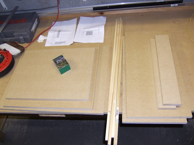
My second attempt was smaller, much sturdier and a lot easier to make. I completed it in two evenings as opposed to two days and with no injuries! I made all the pieces out of 18 mm MDF sheet whereas the first attempt was a mixture of 18 mm, 12 mm and 8mm. All the pieces were rectangles so I got them cut at B&Q where I bought the wood. I used two 1200 mm by 600 mm sheets and all the cuts were free. Here is the kit of parts I came home with.
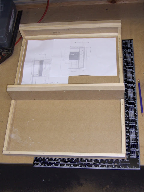
I used 12 mm beading and PVA glue again to make the joints, but this time I used more screws and no nails.
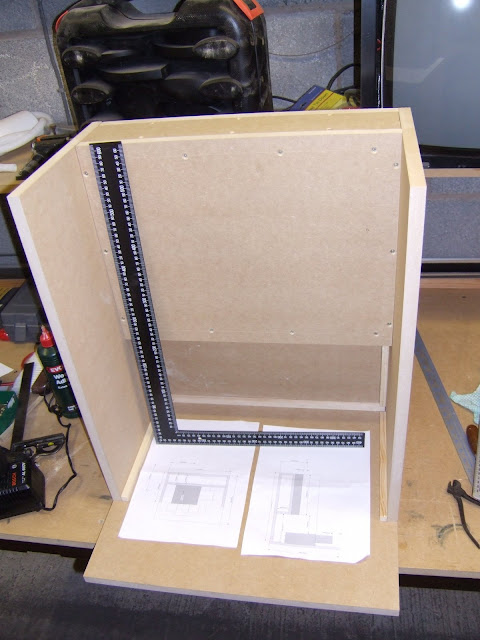
Here is the finished woodwork. No detectable movement no matter how hard I push on it.
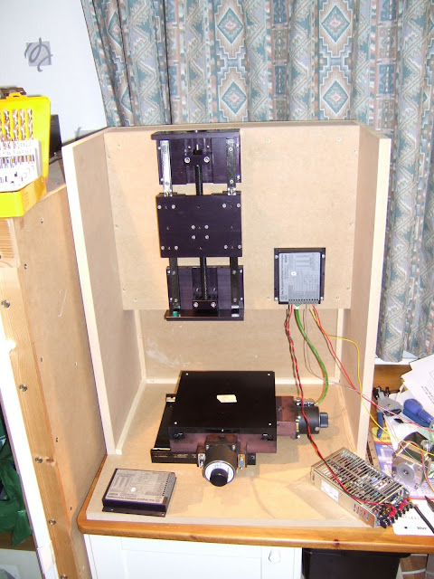
And here it is with the axes installed. The x-axis is wired to its controller and a power supply. This is a small 24V 100W switcher made by Sanken Power Systems. I chose this from the random selection of PSUs I have collected because my z-axis stepper is 24V and the XY controller can run from anything between 24 and 60V. I don't know if I will need a 12V rail yet, I am hoping to get away without it.
I finally found time to update GitHub with some Mendel90 changes that I have had in the works for a long time. The problem with releasing them sooner was that they were all not quite finished and / or would make unintended knock on changes to the kits I was producing. In particular the changes I did to make a Huxley90 in a hurry for the TCT show and the E3D mods kindly contributed by Philippe LUC that conflicted greatly with it, so needed a lot of work to merge.
OpenScad
I also updated to the latest version of OpenScad. The upside was that hull and some of the 2D operations are much faster. I was also able to replace all the calls to minkowski with offset as I was only using it for 2D offsetting. The net result is it is now four or five times quicker to generate the preview and the STL files. The downside is that the 2D sub-system now uses fixed point coordinates but the rest of OpenScad doesn't. This makes it difficult to get 2D and 3D geometry to match up. For example, an extruded circle now has slightly different vertices to a cylinder of the same size. This created a few degenerate triangles requiring that I changed the way I constructed some objects in order to get nice clean STL files.
The solution in the case above was to make the cylinder slightly bigger than the circle used to make the pointer.
On the up side it seems OpenScad has got better at handling unioning exactly coincident faces since I first wrote Mendel90, so I could remove some of my small offset bodges to avoid z-fighting.
Another benefit is that the X end brackets now slice correctly in Slic3r, as the bug that caused internal faces to point the wrong way has now been fixed. Skeinforge doesn't care about face orientation, it just counts edges to work out what is inside and what is outside. Other slicers got confused and filled in the nut cavity.
Along the way I discovered that, although OpenScad now has trig functions that are accurate for multiples of 90 degrees, etc., it doesn't use them in rotate, or vertex creation for circles and cylinders. It converts to radians and uses the library trig functions. Degrees can never be represented accurately as radians in floating point because Pi is irrational, not to mention transcendental. To get round this I now override the built in rotate with a user space version that uses the accurate sin and cos degree functions.
Not surprisingly every STL and DXF file generated is now slightly different numerically but hopefully not dimensionally. I made a stable branch to record the state before these global changes, just in case. GitHub has some excellent image and STL comparison views but unfortunately it gives up if more than a handful of files have changed and there are hundreds in the Mendel90 tree.
Wade's Block
After a few people started to report broken or cracked Wade's blocks I strengthened it a bit around the bearing block. I also made the bearing sockets a bit bigger so there is less stress created pressing them in. Kits from around March 2015 have shipped with this version.
X Carriage
When Philippe LUC created the E3D branch he fixed a few bugs. One of these was that the X carriage top was only 2mm thick, when the design intent was 3mm. This was due to the fan duct using the same variable name. Whoops! I have updated it now in the main branch. I also made the nut traps for the fan bracket screws deeper to allow for longer screws and to allow them to be withdrawn further without loosing the nuts. This makes it easier to remove and replace the duct. Simply removing the washers is an alternative.
E3D Hotend
I temporarily parked Philipp's mods in an E3D branch until I could merge them. I have now updated the master branch to support E3D V5 and V6 hot ends with this one line change to the config file. The generated files for V6 that are different from standard build are in new folders dibond_E3D and sturdy_E3D and I have deleted the temporary E3D branch.
There is no room for the right hand wing nut because it clashes with the hot end's fan. Fortunately the carriage has always had nut traps to allow the screws to be inserted from below. A plain nut above can then be used to secure the extruder.
Primarily the things that change are the Wade's block, the fan duct and the fan bracket. The Wade's block has no extension to avoid losing more Z build height than necessary and a plain screw hole on the right end instead of the hex socket.
The fan duct has to slope downwards to avoid the E3D heatsink. That creates a sloping bridge that is also skewed horizontally. I haven't found a slicer that handles this properly yet, having tried Skeinforge, Slic3r, Cura, Kisslicer and even paid for Simplify3D! I have blogged about their failings in another post here: hydraraptor.blogspot.co.uk/2016/01/a-bridge-too-far. Any other slicers I should try?
Another bug Philippe noticed is that there was almost no clearance between the fan and the belt. Fortunately the belt is twisted so it actually does clear the fan. I have added more clearance as Philippe did. It makes the fan bracket and fan duct 2mm longer. If you print either from the new files be sure to print both or the duct will be misaligned.
I also improved the internal shape of the duct a bit. From this: -
To this: -
It probably doesn't make a lot of difference but a comparative test of various fans and ducts will be the subject of a later post.
Even with the shortened Wade's block the E3D V6 hot end is 4mm lower and the V5 is a bit longer still. If you retro fit it to an old machine you will lose 4mm Z travel. If you are building a new machine then there are alternative files which add 4mm to the height of the frame and lengthen the Z smooth rods and threaded rods on the bom. That also has a knock on effect on the shape of the spool holders and the dust filter. If you use the larger sheets be sure to get the correct size rods and use the correct spool holder parts to match the frame.
New Lighting Options
I redesigned the lighting system I described here to work with some commonly available LED light strips. These consist of an aluminium PCB strip that slides into an aluminium extrusion with plastic end caps, which I discard. Instead of printing a bar to hang the lights and camera from I now add printed end caps to the light strip and uses those to hinge it from the frame edge clips. I then hang the camera from the strip with its own hinge.
The strips come in 500mm lengths but they can be cut at discrete points between every third LED. They are described as "50CM 5050 SMD 36 LED Warm White Aluminium Rigid Strip Bar Light Lamp" and I bought them from bgood2010 on eBay.
I got some from another seller and although the eBay picture looked the same the extrusions where actually not as deep. The STL files on GitHub are for 8.6mm deep extrusions and are generated by light_strip = RIGID5050_290. Setting it to Rigid5050_290 generates the clips for 7mm deep extrusion. Other sizes can easily be accommodated as long as they are rectangular. The definitions are here.
Rather than waste the off-cut I mount it above with a second pair of end caps that clip onto the main light strip. These are set back just far enough to avoid the build volume in the unlikely event you print something tall at the back edge of the bed. This is calculated by the model with lots of trig and Pythagoras maths. Set show_rays = true to see this view showing that the camera and lights are pointing at the centre of the bed and the build volume is clear.
Another light strip that can be selected is this one: FSRP3W, discovered by Alzibiff.
Again the end caps are removed and replaced with printed ones that clip into the screw channels in the extrusion. There is no room for the plug so I just solder the wires on.
It looks neater and gives a more diffuse light but is not as bright as the double strip of 5050 LEDs and is more expensive. I bought it from www.ledlightingandlights.com.
The only problem with these light strips compared to my original Sanken ones is that they are unregulated, so they flicker when the bed switches on and off. I described how I fixed that here. I also need to update the mounting for the Raspberry Pi to accommodate the plethora of new Pis that have appeared since my original design.
Huxley90
The Huxley version is scaled down in the same way as the Sells Mendel was scaled to make the Huxley. It has a build volume of 150mm cubed and uses NEMA14 motors, 6mm smooth rods and M3 fasteners for the frame. There is a good photo of it alongside the full sized machine on Ivor O'Shea's blog post.
The NEMA14 motors have about half the torque of the NEMA17s when driven with the same current. The Y carriage and bed have about half the area hence half the mass, so that is about right. Also a NEMA14 has half the mass of a NEMA17, so the X carriage also has about half the mass. I believe the flex in the middle of the rods is proportional to the length cubed times the weight divided by the bar radius to the power of four. The length of the X rods is almost exactly 75% of the Dibond version and the diameter is obviously 75% as well. The relative flex then boils down to 0.5 / 0.75 = 0.67. So going down to 6mm rods is justifiable as well. Everything scales very nicely physics wise.
As the design is fully parametric shrinking it should have been easy, but because vitamins don't scale perfectly lots of snags arose where things clashed. A typical example was the x_motor_bracket. The NEMA14 motors are smaller but the raised boss around the shaft is the same size. This makes the bracket a different shape and it then needs a support to print it.
Half a truncated teardrop with a crutch!
The heated bed was made with veroboard and coincidentally has the same resistance as a full sized Prusa PCB, so the machine takes the same amount of power but heats up about twice as fast. There is no room on the frame for an ATX PSU, so I used an external XBOX 200W PSU. I couldn't find a spec for the 5V standby rail but it seems to supply enough current to power a Raspberry Pi.
Direct Drive Extruder
The extruder is where the scaling fell down a bit. The original Huxley used a Bowden drive to make the carriage small. I didn't fancy that but I didn't want to have the carriage as big as a geared extruder would need, so I went for direct drive with a NEMA14 and 1.75mm filament.
The filament needs about one third of the force to feed and a Wade's has roughly 1:3 gearing, so a direct drive NEMA17 is about equivalent. The NEMA14 has half of the torque, so it is a bit under powered. I used the smallest drive pulley I had which was a mini hyena from Laszlo Krekacs' Indigogo campaign. Unfortunately I don't think the small diameter version is available now. I could probably make one from a hobbed bolt if I needed to or hob one from scratch.
It feeds PLA fine at 200C but isn't able to pull it off a spool. I will try a spool holder with a central bearing rather than the rim bearings to see if that is low enough friction. If that doesn't work I might try a powered filament supplier like the one on the first Up printer preserved here. Or maybe even try Bowden drive.
The design is parametric so there is a NEMA17 version suitable for Mendel90. I just need to adapt it for a commonly available drive pulley. It should just be a matter of adding a description here.
It can also use the E3D hot end but that doesn't fit between the bars on a Huxley90.
So that is Github up to date and hopefully correct although I haven't tested a lot of these changes. I noticed that Blogger is now a lot worse than it used to be. Headings and pictures are now a nightmare.