Tuesday, 13 November 2007

Disaster recovery

I am pleased to say HydraRaptor is now back up and running after my accident where I connected 240V to a 3.3V logic input. I had to replace most of the electronics, which is annoying because I originally made it out of things I already had, so it cost me nothing, but replacement parts cost me around £180 and obtaining them set me back three weeks.

Things that were destroyed:
  • My ADSL router: a friend kindly gave me a replacement.

  • My PC's serial port: I replaced it with a USB to serial adapter.

  • The Freescale DEMO9S12NE64 evaluation board that I used for my axis controller: next day delivery from Farnell.

  • The EZ430-T2012 eval board that I used for the extruder controller, fortunately the spindle controller was not connected at the time so that survived.

  • The ULN2803 and 7407 chips on my interface board.

  • The optical shaft encoder chip on my extruder.

  • The NEAT MDM7 stepper driver on the X axis. The only thing wrong with it was the direction input was not working. They are opto coupled so it should have been just a simple matter of replacing the opto, but the whole thing is potted in epoxy resin so it is impossible to fix. I managed to find a replacement on the web and I have got some spares on the way as well.

Things that survived:
  • Both power supplies and all the local voltage regulators.

  • The Y axis stepper driver.
  • The X-Y table shaft encoders and Hall effect limit switches.

  • The protected MOSFETs on the extruder controller.

I spent the time waiting for the stepper controller to arrive from the US improving my firmware. I fixed a long standing issue with timing: I was doing my Ethernet comms under interrupt and the stepper motor timing with a higher priority timer interrupt. Unfortunately, the 9S12 does not have nested interrupts, so the interrupt priority is pretty meaningless. I fixed it by moving my comms to the foreground as the machine has nothing else to do in the foreground but process commands coming from the network so there was no point in doing it with interrupts.

I also added acceleration and deceleration to my stepper driving software. I am aiming to lay down 0.25mm filament at 64mm/s. My XY table can easily move that fast but I didn't like the thump I was getting when it started and stopped. It's a bit much to ask it to accelerate a few kilograms to 64mm/s instantly! The datagram for the goto_xyz command now includes a table of delays to use for the first and last n steps. It remains to be seen how much distortion I will get from not moving at constant velocity. At the very least the acceleration will be useful in speeding up the moves when it is not extruding.

Saturday, 27 October 2007

Extruder dimensions

I have been asked for dimensioned drawings of the extruder. I made these by manually inspecting the 3D models in ArtOfIllusion. It is not the easiest application for extracting dimensions so I made 2D drawings in Visio which does have good dimensioning tools. I then made Python scrips to do the milling. My dimensions may differ in places but I did make the extruder from these drawings and it does work. I tightened up some of the hole clearances because my milling machine holds much tighter tolerance than FDM.

This is the motor shaft coupler. I adjusted the slot to suit my GM3 motor. I think there are now two versions of this part. The official design is tapered but this is not necessary with the offset motor mount so I simplified it to a cylinder.


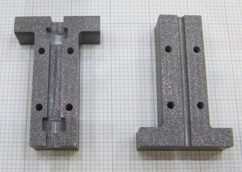
Here is the finished article milled with a 2.22 mm bit. The step on the outside and in the shaft slot are there because my milling tool's shaft is wider than the bit, so to go deeper than 9mm I need to have some clearance. The material is some sort of metal loaded resin.


Here is the clamp drawing I used. It has now been superseded by a larger design. Note that I adjusted the hole for the PTFE to suit my 12mm rod. I think the official design was 10mm but is now 16mm. I also widened the slot to allow the 2.2mm milling tool to get in and added some extra mounting holes to suit my machine.


I milled it from 9mm Delrin.


Here is the pump drawing :-


The poly channel on the official version slopes outwards at the entry but that is only needed for the version without the offset motor.

And here is the milled version :-


The material I used is not as slippery as CAPA so, to reduce friction in the channel, I smoothed it with emery paper, polished it with metal polish and sprayed it with PTFE dry film spray.

I split the motor mount into three pieces for milling from a sheet of 5mm perspex. I fixed the pieces together with M2.5 screws, tapped into the perspex.


If anybody wants the Visio source file it is here:- forums.reprap.org

Tuesday, 23 October 2007

They don't like it up 'em!

How is this for bad luck :-

I was trying to connect a scope probe to the far side of a two row connector on my machine. I made a small hook from a piece of wire with a bit of insulation to get it past the front row.


I inserted this with the power turned off. Unfortunatly, and almost unbelievably, the far end of the wire manage to find its way into a hole leading to the mains live terminal on my solid state relay. That was the only thing on the live side of the mains switch.

Massive bang! Blew the crap out of HydraRaptor and my ADSL router. My PC is crippled is well, it no longer runs at the correct front side bus speed and insists I haven't got an 80 pin IDE cable.

This is the CPU of my axis controller :-


And this the micro from my extruder controller :-


I expect all the rest of the electronics is fried as well, so pretty much the end of HydraRaptor. The only lucky thing was that I was holding the insulation, otherwise it might have been the end of me as well!