This is the motor shaft coupler. I adjusted the slot to suit my GM3 motor. I think there are now two versions of this part. The official design is tapered but this is not necessary with the offset motor mount so I simplified it to a cylinder.

Here is the finished article milled with a 2.22 mm bit. The step on the outside and in the shaft slot are there because my milling tool's shaft is wider than the bit, so to go deeper than 9mm I need to have some clearance. The material is some sort of metal loaded resin.

Here is the clamp drawing I used. It has now been superseded by a larger design. Note that I adjusted the hole for the PTFE to suit my 12mm rod. I think the official design was 10mm but is now 16mm. I also widened the slot to allow the 2.2mm milling tool to get in and added some extra mounting holes to suit my machine.

I milled it from 9mm Delrin.

Here is the pump drawing :-

The poly channel on the official version slopes outwards at the entry but that is only needed for the version without the offset motor.
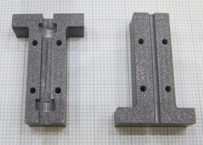
And here is the milled version :-

The material I used is not as slippery as CAPA so, to reduce friction in the channel, I smoothed it with emery paper, polished it with metal polish and sprayed it with PTFE dry film spray.
I split the motor mount into three pieces for milling from a sheet of 5mm perspex. I fixed the pieces together with M2.5 screws, tapped into the perspex.


If anybody wants the Visio source file it is here:- forums.reprap.org


