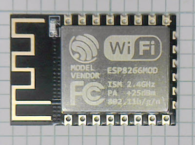
I plan to make a few projects based around ESP-12F WiFi modules. These are postage stamp sized modules containing an ESP8266 chip plus 4MB of flash. The ESP8266 chip is a 32 bit MCU with an integrated WiFi transceiver and TCP/IP stack. They come programmed as a WiFi modem but they can be reprogrammed with the Arduino IDE to do other things in addition to the WiFi. Great for IOT applications because they are so small and cheap (less than £2) but reasonably powerful. A lot more powerful than an Arduino, for example, but with less I/O.
The solder pads are on a 2mm pitch, so they are often used with a breakout board to adapt them to 0.1" pitch for breadboard or perfboard, etc. That adds cost and increases the size somewhat because the through hole pins need to be outside the perimeter of the module. I solved the problem another way, by using a 3D printed wire guide that routes wires from the 0.2mm pitch holes to the nearest 0.1" hole, minimising the space used and costing virtually nothing.
The holes in the module are quite small so I use stripped wire wrap wire. I push it through the module, down through the guide, which routes it to the correct hole in the perfboard. I fold the top over, solder it to the module and trim it. I do the four corners first and pull them tight and solder underneath to secure the module.
Here is a module mounted on perboard.
It doesn't use any extra board space outside the 0.1" holes it uses. I.e. the adjacent holes are all usable.
I didn't break out the end connections because they are not very useful. They are all GPIO lines used internally for the flash. I read it is possible to free up two by removing the can and re-configuring the flash chip to use a two bit interface instead of four bits, but that is too much hassle for me.
Here is the OpenSCAD that produced the adapter: -
The only notable thing is the squeezed wall definition, see my previous post.
Tuesday, 3 April 2018
Avoiding voids
The thinnest practical wall you can print, (with Skeinforge at least), is two extrusion widths wide. Any bigger leaves a gap, until you get to three extrusions wide, and then you get infill in between them.
If the wall is exactly two extrusions wide then they only touch tangentially and have a weak bond because the edges of the filament are rounded.
I discovered that if you make a wall even thinner then Skeinforge still lays down two paths equal to the extrusion width but places them closer together. This is because it always offsets inwards by half the extrusion width, even if the resulting paths overlap. I found I can make use of this to squash the plastic together, making a stronger wall with less voids.
An optimum amount of squeeze is to place the nozzle aperture just free of the flat part of the first path when extruding the second. The width to make this happen is $extrusion\_width - layer\_height / 2 + nozzle\_aperture / 2 + extrusion\_width / 2$.
Of course, despite what Skeinforge thinks, the plastic volume can't overlap, so regardless of where the nozzle is the minimum width the wall can be is $2 * extrusion\_width - layer\_height * (1 - π/4)$ due to the volume of plastic extruded, i.e. if it manages to completely fill the voids. This is shown below: -
The grey area is where the edge would have been with the wall two extrusion widths wide. There isn't much difference, and depending on the viscosity of the plastic, the real width should be somewhere in between. But the big difference is the walls are strongly fused together. The top void should be completely filled because it is right under the nozzle, leading to a smoother top surface. And the bottom void has more chance of being filled due to the back pressure caused by the filament having to flow more to the right.
To put some numbers to the diagrams, these have been drawn to scale for 0.25mm layer height and 0.5mm extrusion width, 0.4mm nozzle. The requested wall width is 0.825mm but the volume of plastic means it must be at least 0.946mm, only 0.054mm less than the original 1mm wall.
I made a test script that makes a box with two 1mm walls and two 0.825mm walls.
Here is a corner of the box under a microscope. The wall on the left is seamlessly fused and the wall on the right clearly has a void.
The wall comes out a bit thinner than the theory predicts, I am not sure why, maybe the increased pressure causes the plastic to feed a bit slower.
I used this technique to make the Mendel90 fan guards a lot stronger part way through production because I had some fall apart one day when my filament was a bit undersized.
It would be nice if the slicer could do this automatically, so you can keep a 1mm wall in the design, but it would make it by extruding one side of the wall as normal but the other side it would offset the nozzle to fill the voids and then extrude a little more plastic to make it still 1mm thick.
In fact it should really do this anytime it is extruding against another extrusion path. E.g. when doing multiple outlines and when doing infill. I.e. the only time the tool path of the nozzle should be down the centre of the extrusion path is when there is nothing either side, or it is enclosed on both sides. And in each of these three cases a slightly different flow rate would be needed to get the new exposed edge in the correct place.
Saturday, 2 December 2017
Fretting corrosion
Long ago I noticed friction fit connectors are not reliable in 3D printers: hydraraptor.blogspot.co.uk/2011/06/reliable-connections. For example, 0.1" Molex connectors that are rated for 3A burn out when only carrying 1A motor currents. Even signal connectors on HydraRaptor lose contact and need re-seating occasionally. I figured it must be due to vibration and / or thermal expansion and contraction.
It is one of the reasons I choose the Melzi electronics for Mendel90, i.e. because it has screw terminals instead of Molex connectors that are common on other boards like RAMPS. While looking at some connectors for another project I came across the term "fretting corrosion", which is exactly the problem that causes failed connections when you have vibration or thermal movement. There is a marketing video explaining it here:
Basically contact mating points need to be gas tight to prevent corrosion and any relative movement breaks the gas tight seal. You can now get connectors that have sprung female parts to absorb any motion and prevent this mode of failure. Worth considering if you are designing a 3D printer.
It is one of the reasons I choose the Melzi electronics for Mendel90, i.e. because it has screw terminals instead of Molex connectors that are common on other boards like RAMPS. While looking at some connectors for another project I came across the term "fretting corrosion", which is exactly the problem that causes failed connections when you have vibration or thermal movement. There is a marketing video explaining it here:
Subscribe to:
Comments (Atom)


