Sunday, 16 December 2007
Chopping up chopping boards
I have tried many other surfaces including various woods and metals (with and without primer), melamine and several other types of foam board but nothing worked. Obviously HDPE sticks to HDPE so I decided to investigate that further.
My first idea was to use a thin sheet of HDPE cut from a milk bottle. This makes a nice surface to extrude onto but the problem is holding it down. I first stuck it down with double sided tape but the heat melts the glue. Sticking it to a sheet of aluminium to take the heat away improved matters and I was able to get slightly less warping than with foam board.
To compare the warping on different base materials I made a test shape that is a 40mm x 10mm x 20mm open box with 1mm walls and measured how much the corners lift using a simple jig.
With foam board I was getting 0.83mm lift between corners and the middle. With HDPE stuck to aluminium I got 0.76mm. Not much better because the glue of the sticky tape stretches under the curling force.
I needed a thick HDPE base and I had heard that plastic kitchen chopping boards are made from HDPE. I bought a new one from ASDA which looks like this :-
It is 5mm thick, opaque and quite rigid. I realised it was very different from the other chopping boards we have which I think came from IKEA.
These are 10mm thick and made from a softer, more translucent plastic. To find out which was HDPE I used the flow chart on this website www.texloc.com/ztextonly/clplasticid.htm. I concluded the thin hard one from ASDA is HDPE and the thicker softer one from IKEA is PP. HDPE seems to stick equally well to both of them but the HDPE one warped a bit when it was only held down with masking tape, so I decided to go with the PP one. I cut it up and bolted it down to my XY-table. It was a bit curved due to years of dishwasher use but bolting it down pulled it flat.
Surprisingly, if I lay down a raft at 200°C it sticks well but can be easily prized off again with a penknife. The board is marked slightly but it can be reused over and over again.
I extrude the object at 240°C so that it welds to the raft and itself, and I turn the fan on after the first layer so that the object cools to room temp as fast as possible.
The board is strong enough to hold the object completely flat while it is attached but when it is removed it does still curl a bit. I measured 0.44mm on my jig so that is about half the curling I was getting with foam board. Other than extruding onto a convex surface, I think that is the best that can be achieved for that shape with HDPE at room temperature. Here are the three tests side by side :-
Next I will look at different solid shapes to see if they warp more or less.
Tuesday, 13 November 2007
Disaster recovery
Things that were destroyed:
My ADSL router: a friend kindly gave me a replacement.
My PC's serial port: I replaced it with a USB to serial adapter.
The Freescale DEMO9S12NE64 evaluation board that I used for my axis controller: next day delivery from Farnell.
The EZ430-T2012 eval board that I used for the extruder controller, fortunately the spindle controller was not connected at the time so that survived.
The ULN2803 and 7407 chips on my interface board.
The optical shaft encoder chip on my extruder.
The NEAT MDM7 stepper driver on the X axis. The only thing wrong with it was the direction input was not working. They are opto coupled so it should have been just a simple matter of replacing the opto, but the whole thing is potted in epoxy resin so it is impossible to fix. I managed to find a replacement on the web and I have got some spares on the way as well.
Both power supplies and all the local voltage regulators.
- The Y axis stepper driver.
The X-Y table shaft encoders and Hall effect limit switches.
The protected MOSFETs on the extruder controller.
I also added acceleration and deceleration to my stepper driving software. I am aiming to lay down 0.25mm filament at 64mm/s. My XY table can easily move that fast but I didn't like the thump I was getting when it started and stopped. It's a bit much to ask it to accelerate a few kilograms to 64mm/s instantly! The datagram for the goto_xyz command now includes a table of delays to use for the first and last n steps. It remains to be seen how much distortion I will get from not moving at constant velocity. At the very least the acceleration will be useful in speeding up the moves when it is not extruding.
Saturday, 27 October 2007
Extruder dimensions
This is the motor shaft coupler. I adjusted the slot to suit my GM3 motor. I think there are now two versions of this part. The official design is tapered but this is not necessary with the offset motor mount so I simplified it to a cylinder.
Here is the finished article milled with a 2.22 mm bit. The step on the outside and in the shaft slot are there because my milling tool's shaft is wider than the bit, so to go deeper than 9mm I need to have some clearance. The material is some sort of metal loaded resin.
Here is the clamp drawing I used. It has now been superseded by a larger design. Note that I adjusted the hole for the PTFE to suit my 12mm rod. I think the official design was 10mm but is now 16mm. I also widened the slot to allow the 2.2mm milling tool to get in and added some extra mounting holes to suit my machine.
I milled it from 9mm Delrin.
Here is the pump drawing :-
The poly channel on the official version slopes outwards at the entry but that is only needed for the version without the offset motor.
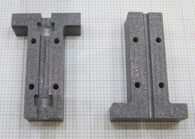
And here is the milled version :-
The material I used is not as slippery as CAPA so, to reduce friction in the channel, I smoothed it with emery paper, polished it with metal polish and sprayed it with PTFE dry film spray.
I split the motor mount into three pieces for milling from a sheet of 5mm perspex. I fixed the pieces together with M2.5 screws, tapped into the perspex.
If anybody wants the Visio source file it is here:- forums.reprap.org