Loading [MathJax]/extensions/tex2jax.js

Tuesday, 10 April 2007

Trouble at' mill

Having established that the axes were all working well I decided to do some tests to check the feasibility of milling PCBs. I originally planned to use a Dremel but its shape looked difficult to mount. I saw a cheap alternative that was cylindrical so I decided to give it a try.

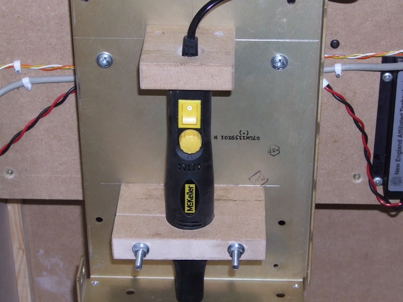
I made some mounts out of MDF and these were bolted onto a 2 mm aluminium plate which had some folds in it for strengthening. I could not find a source of countersunk bolts long enough to go through the top mount. Instead I used some shorter ones and made captive nuts out of PolyMorph. I did this by first drilling clearance holes from the back of the mount to a depth just longer than the bolts. I then drilled 5 mm holes through the thickness of the MDF to meet them. I filled these with molten PolyMorph. When it had set I drilled it for tapping but I found I could just screw the bolts in and they cut their own thread. This technique seems to make a successful fastener system.


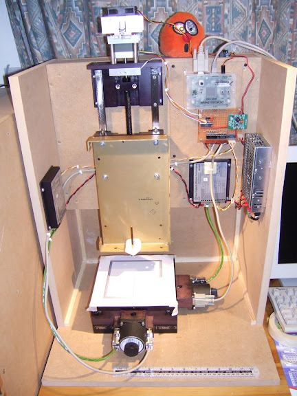
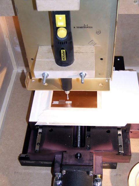
I asked a friend who works for a company that owns a professional PCB mill what they place under the PCB while it is being drilled. He was kind enough to send me a sample. It is 2 mm hardboard laminated with a thin layer of hard, melamine like, substance on each side. I have not found a source for this yet but my wife, ever keen to see "junk" turned into something useful, suggested I used some laminate flooring offcuts we have in the garage. I will give this a try, but for my initial test I used the hardboard sample. I just taped it to the top of my XY table with masking tape and taped a piece of PCB material on top. The arrangement is shown below :-


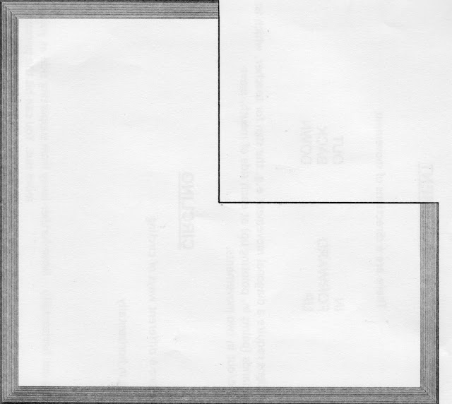
And here is a magnified view of the results :-


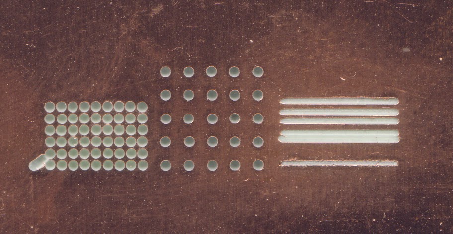
The diagonal on the far left is where I broke a drill due to a typo in the code: step_x instead of step_z. The drill made a valiant attempt at being a milling bit before it snapped. Not a good start, this could get expensive!

The holes on the left are 1 mm on a 50 thou grid. So far I have tried to keep all the units in this blog metric but PCB measurements are traditionally done in 1000 ths of an inch because most component leads are on a 0.1" grid. Again this was a bug but it turned out to be a good test to show drill run out. The gaps between the holes should be 0.27 mm or about 10 thou.

The holes in the middle are on a 0.1" grid which was my original intention. The holes don't actually go all the way through due to end play in the drill.

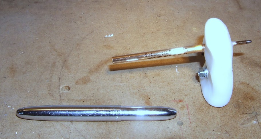
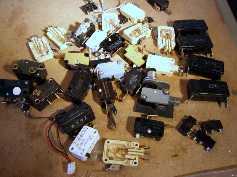
The bottom slot on the right was done with the conical tool shown in the picture below :-


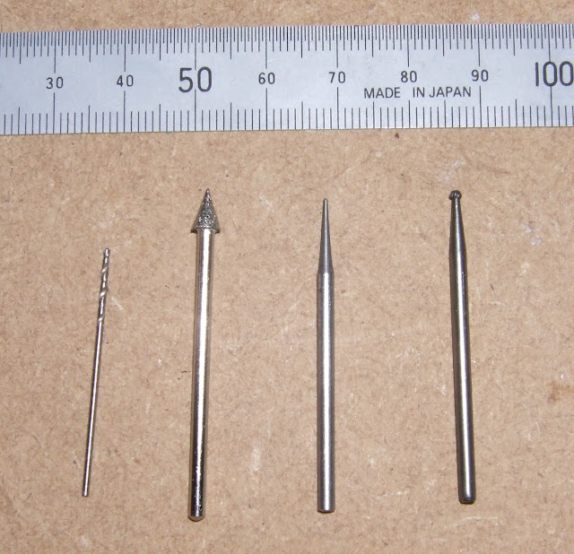
This has quite a fine tip but an abrasive surface rather than cutting flutes. I estimate the channel is about 20 thou but the edges are a bit ragged, particularly the top edge. The tool rotation was clockwise and the travel left to right. This means the bottom edge was climb or down milled and the top edge conventional or up milled. Climb milling is recommended for a better finish so I need to organise my tool paths to go clockwise around the outside of tracks.

The three tracks were produced with a rose burr tool like the one on the far right but smaller. The remains of it are shown in the middle. I snapped it after the test with another accident. This tool created a smoother cut. Again, the bottom edge is cleaner. The bottom track is about 20 thou, the middle one 10 thou and the top one 15 thou. The gap between tracks is about 30 thou.

My target for through hole PCBs is 10 thou tracks and 15 thou gaps. This allows one to get a track between two 60 thou pads 0.1" apart, i.e. between the legs of a chip.

Things I learned from this experiment :-

  • Not surprisingly, the cheap (£20) drill was not up to the job. It has about 1 mm end play and noticeable lateral play. It is also very noisy when mounted on the machine. I have ordered a 30000 RPM 600W laminate trimmer for £26.49. Again, I will not know the quality of the bearings until it arrives, could be another mistake.


    If that does not work I might try a Dremel or perhaps one of these :-


    This is an 800W router spindle motor for about £80.

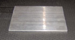
    There is a good article on how to make your own PCB router spindle here but I think my lathe is too small.


  • The 2mm aluminium plate is not stiff enough, I got a 6mm slab from eBay to replace it.


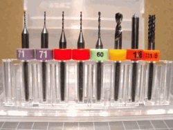
  • The milling bit, before I broke it, was too big. I got an eight piece "carbide circuit board maker" kit from Drill Bit City for $23. They were very helpful and efficient. Again the good stuff is on the wrong side of the pond so the shipping was another $12.


    They also sell carbide end mills down to 5 thou. These are quite pricey and delicate but I might try some when the software is stable. I will need smaller clearances for fine pitch surface mount.

  • I need dust extraction and it needs to be a fairly strong suction to lift the copper chips. I can buy a 1300W vacuum cleaner from ASDA for about £17.

Despite the deficiencies noted above I think the test was reasonably successful. In fact the current set up could probably produce a working PCB. I will get the software written and debugged before I fit the new parts. A 600W router could do a lot of damage! It would bring a whole new meaning to the phrase "software crash".

Monday, 9 April 2007

Pen pusher

As others have done before me, I decided to test the Cartesian system by turning it into an over engineered pen plotter. I used the refill out of a Fisher Space Pen which apparently "is the most advanced writing instrument in the world". If so, when controlled to a precision of 6 μm, it must make HydraRaptor the most advanced writing machine in the world! I can't think what I would use it for apart from forging signatures.

I suspended the pen from the z-axis on a random bit of aluminium using a lump of PolyMorph. This made a perfect mount because I pushed the pen through while it was still molten. There was no play, but if the z-axis were to overshoot, it would just pop the pen out rather than ram it into the table.


I ran a simple program which went from the origin to one edge, around three sides and back to the origin again. It then repeated this, stepping in by 0.2 mm each time. I soon realised the line width was bigger than 0.2mm so I stopped it and ran it again with a step size of 0.4 mm. This left a gap between the lines and produced the pattern below.


Here is the top left corner magnified.


You can see the corners are pretty good considering the table was travelling about 4 cm per second with no acceleration, deceleration or pause as it turned. At this resolution the graininess of the paper is the most significant distortion.

The paper was stuck to the metal top of the XY table with masking tape. I set the height of the pen by stepping it down until it just started to leave a mark on the paper and then one step more. The paper was about 0.1 mm thick so that meant the pen was pressed about half way into it. As you can see from the first picture the pen never left the paper so the table must be pretty flat and its movement true. Here is the machine in action :-


The results look promising, time to have a go at milling next.

Sunday, 8 April 2007

Know your limits

The XY table boasts Hall effect limit switches with a repeatability of ±2.5 μm so I should have no problem getting a repeatable homing position to the nearest 6 μm step. They do however have quite a lot of hysteresis and activate some distance from the actual physical end stop. In my first cut of the code the homing routine steps quickly until it sees the negative limit and then steps slowly forward until it sees the limit go away. It sets the position at this point and then ignores the limit from then on so it can achieve the full range of travel. I am not sure whether both positive and negative edges of the limit signal have the same accuracy. I will get more idea when I write the shaft encoder software. These have an index pulse so, no matter how inaccurate the limit switch is, I will be able to get an absolute fix on the position to within one shaft encoder step, which is the same as one stepper microstep.

I haven't used the positive limits yet and I can't think of a reason for needing them except for possibly an automated self-test. I will use the shaft encoders to check that the table is where I think it should be and halt if I find a significant discrepancy. That would indicate a firmware bug, tool crash or hardware failure.

The z-axis did not come with limit switches so I had to improvise. I wanted repeatability to within one half step, i.e. 50 μm. The software knows what the shaft position modulo 8 is because it knows the phase pattern applied to the motor. That means it only needs a limit switch with repeatability better than 0.4 mm. I decided to try a micro switch to see if I could find one good enough. As you can see I have managed to amass quite an extensive collection!


I picked one of the small ones on the bottom right and it seems to do the trick. Again it has significant hysteresis as one would expect. My homing routine steps upwards at speed until it activates the switch and then steps down slowly until the switch opens again. At this point I AND the motor position with 7.

Once the homing was sorted out I was ready to test the accuracy.