Saturday 6 February 2016

Cool maps

The aim of making the instrument described in the last post was to be able to quantify the cooling effectiveness of various fan and duct combinations by sampling the airflow at a grid of positions around the nozzle.

I attached the denuded bulb to the terminals such that it was pointing vertically upwards. I then placed the Coolometer on the bed with the bulb filament aligned with the nozzle at the centre of the bed (0,0).


I originally planned to clamp it somehow but instead I just placed it on some anti-slip matting and set the Y acceleration to a very low value.

My printers are controlled by Raspberry Pis so it was straightforward to attached the Coolometer to the second USB port. I control both it and the printer with the following Python script that runs on the RPi.

I made the Coolometer command acknowledgement ok, the same as Marlin, so I could use the same do_command() function to talk to both of them by passing the serial port.

The script scans in X and Y taking a cooling reading at each grid point. It generates a file called fanmap.dat that consists of a list of XY coordinates with a cooling reading in milliwatts. The file format can be read by gnuplot to draw graphs. This is the first time I have used gnuplot. I normally draw graphs with spreadsheet programs but this is a lot more powerful and very easy to use.

This simple gnuplot script: -

produces 3D plots like this: -


The 3D view looks cool and is good for interactive examination because you can rotate it with the mouse. A better view for a static picture is from above, which can be obtained by set view map. These are referred to as heat maps in gnuplot parlance but by reversing the palette they become cool maps!


Here is the script I used: -
It labels the colour key with the minimum, maximum and average cooling values in mW. Gnuplot is fantastically powerful and flexible but it took me a while to achieve the exact view I wanted.

Each reading is averaged over 100 samples in about two seconds, so it takes about an hour to do a scan of 80 by 90mm in two mm increments.

This is the first plot I made and was done on my Huxley90 because that machine is next to my desk. It is fortunate I did this first as I was expecting some difference in airflow from front to back but was surprised to see a big difference side to side. Had I scanned the Mendel90 duct first I would have attributed that to its asymmetry, but the Huxley90 duct is left right symmetrical. Here it is in the same orientation as the 3D graph: -


The only explanation that I could think of to cause this imbalance is the anti-clockwise rotation of the fan.

To test this hypothesis I mounted the fan upside down so it was spinning clockwise, but then it was sucking rather than blowing of course. The cooling effect was much less, as expected, but was now stronger on the right than the left.

Another experiment I did was to watch smoke from a joss stick going through a naked fan. I had to run the fan very slowly to be able to see smoke coming out the other side. The smoke going in was a tightly twisting vortex looking like a micro tornado. Coming out it was rotating more slowly with a  bigger diameter.

So I think that because the air-stream is rotating anti-clockwise it likes to exit the duct on the left hand side where it is travelling downwards and less so on the right hand side where it is travelling upwards. The effect seems more marked with the small 40mm fan I used for the Huxley90. This is possibly because the depth to width ratio of that duct is bigger, so the flow is more free to rotate.

Moving on to the fan duct and fan supplied with the Mendel90 Dibond kits this is the plot I got: -


As you can see the overall cooling effect is better, as to be expected with the bigger 60mm fan. There is a less pronounced left right difference but there is an odd cold lump front right. I thought this might be something to do with the jet from the cold end cooling hole at the back or perhaps the hot end affecting airflow. I removed the hot end and blocked the hole and neither made any significant difference.

My hypothesis is that the air rushes around each side of the circular part of the duct in opposite directions and collides at the front and then spills out. I.e. the air has significant momentum, so it prefers going around the outside of the duct loop to exiting the slot in the bottom. When it hits the air coming from the opposite side it has no choice but to exit. The lump is displaced to the right because the left stream is more powerful.

Odd that the ring of maximum cooling is smaller diameter when the output part of the duct is identical to the Huxley one.

The next thing I tried was the same duct with a GELID Solutions Silent 6 fan suggested by +Neil Darlow.


This claims to have "Optimized Fan Blades" and "High Airflow and High Static Pressure" as well as "Silent Operation" and "Long Lifetime". Here is a comparison of the things I could measure compared to the original fan: -


Current Power Speed Noise
Silent 6 @ 12V 0.103 A 1.2 W 3060 RPM 47.5 dB
Original @ 12V 0.209 A 2.5 W 3600 RPM 53.5 dB
Original @ 9V 0.136 A 1.2 W 3060 RPM 48.3 dB

I measured the noise at 15cm rather than the normal 1m because my sound meter only goes down to 40dB. The fan was running in the duct and placed on a block of foam so the table did not act a sound board.

I used the tacho signal on the yellow wire to get the speed. It produces a square wave with two cycles per revolution. I found that the supplied fan had no output on the yellow wire and after I disassembled it I found the components for it: a PNP transistor and a resistor were not fitted. In fact the only electronic part is a hall effect chip with complementary outputs. That feeds a two phase motor with two pairs of coils in series. I added the missing components to make the measurement. Interestingly the transistor is driven from one of the coils so it works even when the fan is not powered as long as it is spinning fast enough to generate enough voltage to turn the transistor on.

The data shows what I expected: that most of the noise reduction comes from the reduced speed. If the original fan is driven from 9V it rotates at the same speed as the Gelid one and takes about the same power. It is slightly noisier, which I put down to the fact the Gelid has a smoother leading edge on its blades. They also have more curve to them giving it a steeper pitch, so it can potentially move more air at the same speed.

This is the cool map from it: -

Compared with the original fan it does produce a slightly higher peak and average cooling effect with 6dB less noise, so it does do what it says on the tin. However it has the unexpected effect of changing the air distribution significantly.

I tried running the original fan with 50% PWM. All that did was reduce the airflow, it didn't change the distribution significantly.

So it seems that subtle changes to the shape of the fan blades greatly affect the airflow pattern at the exit of the duct. Who would have guessed that?

Next up is the version of the fan duct to suit the E3D V6 hot end that proved so challenging for slicers. This has to slope downwards to fit underneath the E3D's fan assembly. It is also a bigger diameter to clear the bigger heater block assembly.


Not too surprising to me by now this has a massive and unpredictable effect: -

I have no real explanation for why this seems to have a quarter of the circle missing. Looking at the plot one would think there is a blockage or a hole in the duct but that isn't the case. I think it is a consequence of two streams of air hitting each other head on. If you think about it that would create a chaotic result.

There are a lot of alternative Mendel90 fan duct designs on Thingiverse so I decided to test a few of those.

This is a 40mm duct by sivar2311: -


Less cooling than my 40mm Huxley90 version and very uneven.

This is an alternative 60mm duct for the E3D hot end by +Daniel Bull that has the fan mounted vertically :-


Compared to my original design this gives a higher average cooling but a lower peak. It too has a quarter of the loop missing and the air that should come out there seems to shoot off forward instead. Mounting the fan vertically seems to give a bit more flow, presumably because the air doesn't have to turn a corner, but it seems to be less even, possibly due to the rotation having a bigger effect.

After I designed Mendl90 I learned that radial blowers are more suited to pushing air down a small duct. Axial fans are fine for pushing large volumes of air down a large duct but radial fans generate a higher pressure so are better suited to making smaller jets.

This a duct for a 50mm radial blower by kiefer :-


I got the blower from RobotDigg but it seems to be slightly different to the one pictured and has three wires, not two.


 It rotates at 7200 RPM, takes 250mA and produces 56 dB at 15cm. So it is a lot more powerful than the original fan but more compact with the air coming out of a much smaller aperture.

It gives significantly more cooling and there aren't any gaps in the ring. It does seem to suffer from the air coming from both sides and colliding problem at the front. That seems to result in a high pressure jet spilling inwards and a lower pressure stream spilling outwards at the front.


Conclusion

When I designed the Mendel90 duct my aim was to achieve even cooling of the part without cooling the nozzle. The default duct with the original fan seems to give the most even cooling but I now think that is a complete fluke. Small changes such as the height of the duct, or the shape of the fan blades has a dramatic effect. This leads me to think that the airflow with an axial fan is chaotic due to the presence of vortices arising from its rotation.

A radial blower seems to be the way to go as it produces more cooling and the air coming out of it isn't rotating. I would mount the blower with its aperture pointing forwards to avoid the air needing to turn a right angle. Rather than have the air flowing around the circle in both directions I will try a p shape where the air goes around in one direction and then meets itself travelling in the same direction. I think this will create a vortex airflow that emerges more evenly around the circle.  I expect the shape of the junction might be critical. As far as possible I will try to keep the cross section constant to avoid Bernoulli effects.

So in all I managed to use three new tools (fritzing, CodeBender and gnuplot) and discovered a few facts about fans and airflow, so I learned a lot doing this project.

Fluid dynamics is obviously a massive subject and I learned this morning that it isn't a solved problem mathematically, there is a $1M prize outstanding. As ever, the closer you look at things the more complicated they get.


Friday 29 January 2016

Quantifying cooling

A few months ago +Neil Darlow mentioned that he had replaced his Mendel90 fan with a quiet version and it seemed to give better cooling results. This made me curious because quieter fans of the same dimensions generally spin slower and produce less airflow. So I purchased one to compare but then realised I had no better way of judging its efficacy than holding my finger in the air stream to feel the breeze. With these two fans it was too close to call.

After a bit of Googling I found that an easy way to measure localised airflow is with a hot wire anemometer. These heat a wire by passing a current through it and then measure how much the airflow cools it. The current and voltage can be used to determine both the resistance and the power dissipation using Ohm's law. The resistance can then be used to determine the temperature knowing the thermal coefficient of the metal that the wire is made from. The extra heat loss due to the airflow is proportional to the square root of the flow rate.

A popular circuit configuration is a constant temperature anemometer as described here, but note the op-amp inputs are labelled incorrectly. An op-amp is used to adjust the voltage across a Wheatstone bridge to keep it in balance. The bridge consists of three fixed resistors and the hot wire, so when it is balanced the wire has a known fixed resistance determined by the other three. Because the power is controlled to keep the resistance constant it follows that the temperature of the wire is constant. The voltage on the bridge can then be used as a measure of the heat carried away by the airflow.

Tungsten is commonly used for the hot wire, presumably because it has a reasonably high resistivity, temperature coefficient and resists oxidisation. I hatched a plan to use a small light bulb with the glass removed, mount it on the bed of a printer and move it around under the fan duct to plot a map of the airflow.


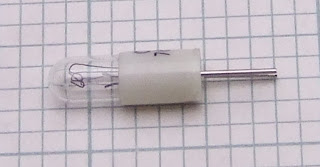
This is a small 12V 0.8W bulb. Its cold resistance is about 15Ω but more than ten times that when hot. This is why bulbs take a massive surge current for a few milliseconds when they are switched on.

I was wondering about how I was going to calibrate the airflow reading but then realised that the flow rate is not actually what I am interested in. It is the cooling effect the airflow has, which is what I am directly measuring. The result is simply the extra power needed to maintain a target temperature and is a measure how fast the bulb filament is being cooled. So rather than an anemometer I decided to call it a coolometer. Unfortunately Futurama used that name first. Rather than displaying megafonzies mine displays milliwatts!

This is the circuit that I came up with: -


R1, VR1 and the bulb filament connected across J3 form the bridge that is maintained in balance by U1, Q1 and Q2. The CA3140 is a fairly old op-amp that I have had lying around for more than 25 years but it does still seem to be available. It was notable at the time for the fact its inputs are happy at or slightly below the negative rail, so it doesn't need a negative supply, unlike a lot of early op-amps like the 741. It also has a very high input impedance but that is no benefit here. Its output can't go higher than 3V when driven from a 5V supply and although it can source 10mA it can only sink 1mA.

Q1 is a PNP emitter follower that amplifies the current that can be sunk and also acts to shift the output voltage range 0.7V higher. R3 and R2 further shift the voltage so the output swing can turn Q2 fully on or off. The side effect is they reduce the loop voltage gain but Q2's voltage gain will more than make up for that. It further boosts the current to drive the low resistance bulb and allows the bridge voltage to swing over the full supply range. If I was designing using modern components I would use one of the true rail to rail op-amps from Maxim and save a transistor.

VR2 is an offset null adjustment. I didn't think one would be needed at first because a small input offset isn't going to affect the output much in this circuit. However I soon realised that there are two stable states, one where the bridge is in balance and the other where the voltage supply to the bridge is zero. To force the circuit into the non-zero state I had to ensure there was a small but finite negative input offset.

I was a bit worried that adding more voltage gain after the op-amp might cause it to oscillate like my ULDO regulator did. However it appears to be stable with just the op-amp's internal frequency compensation. That must be because the transistors have a much higher frequency response than the op-amp, so don't add much extra phase shift within its bandwidth.

To measure the results, display them and send them to a serial port I used a MicroView. This is a tiny module combining an OLED display and an Arduino. I got four of these from the Kickstarter campaign. They are relatively expensive for what they are but I got four for the price of two because Sparkfun sent the first ones out without a bootstrap and had to replace them all. Since I have an ISP programmer it was trivial to install bootstraps into the first two.


The MicroView measures the voltage on the bridge and also the voltage across the bulb. With those measurements and knowing the value of R1 it can calculate the resistance and power dissipation of the bulb. Given the thermal coefficient of tungsten and cold resistance of the bulb it can estimate its temperature.

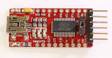
I didn't use the USB serial converter that goes under the MicroView because I wanted a micro USB socket rather than a full sized plug and I also wanted a lower profile, so I used one of these instead.

I removed the right angle connector and fitted pin strips down the two sides. They appear as J1 and J2 in the schematic. I also removed the 3.3/5V jumper and replaced it with a wire link to lower the profile.

Because I wanted to test the circuit on a breadboard and then move it to perfboard I decided to try out fritzing. I was impressed by its ease of use. One bugbear of mine with traditional ECAD is the separation of the schematic and layout into different programs. You have to export your schematic as a netlist and import it into the layout program. Then there are horrible things like back annotation and cross probing. I have long argued it should be a single model with two views that are kept in sync. Having written a UML CASE tool myself, which has 15 different tabbed views of the same database that are always in sync I know this isn't too difficult to do.

Fritzing has breadboard, schematic and PCB views that are all synchronised. You can add, remove and connect components in any view and it will be reflected in the others. One thing I found quirky was that nets seem to preserve the order of connection, so you have to route the PCB or breadboard in the same order as the schematic. You can get around this by making tracks double back over themselves but in my mind a net should represent connectivity without an order of connection.

You can find the fritzing project here: fritzing.org/projects/coolometer

Here is my perfboard layout: -


You can see the offset null pot was a late addition connected with flying leads on the back. I left the un-routed rats nest to represent those.

I am not a fan of the radial components being shown on their sides. It makes some sense for simple breadboard projects but I would prefer a strict plan view.

The breadboard view can show a traditional breadboard or  stripboard. The perfboard view is just a variation of the stripboard pattern, it simply replaces the strips with pads. The problem is that with perfboard you also need to put wire tracks on the back of the board as well as jumpers on the top. There is no way to represent that in fritzing 0.9.2, so I had to print it out and hand mark the underside tracks with a pen to actually be able to build it.

There are quite a lot of part libraries about that contain parts aimed at hobbyists like the MicroView. As they are contributed by different people / companies there are inconsistencies in the sizes and style of schematic symbols. For example the pots should be the same size as the other resistors and being trimmers should have a flat slider instead of an arrow. The arrow should meet the zigzag, not go through it, that would be a two terminal variable resistor. This appears to be a cross between the two. As fritzing appears to be aimed at education I think it is important for the symbols to be correct.

I do like the old school resistor symbols but they were replaced with boring boxes by standards organisations in the nineties if I remember correctly.

I failed to find a part for the CA3140, so I used a random op-amp that had a sensible looking symbol. Unfortunately the offset null pins of an OP27 didn't match the footprint of a CA3140, hence why it appears to be connected to an NC pin on the schematic. I tried to modify it to match my part but failed. Part creation is external to fritzing.

I also made a PCB layout just to try it out, I have no intention of making a PCB as this is a one off for an experiment. Auto route works but is ugly, as always, so I hand routed it as I always do.


A view with the pictorial version of the components would be nice. Note that the footprint of the pots is different to breadboard view. It actually matches the pots I used though.

Again it is very easy to use for simple designs like this. I think it is limited to two layers and I don't think it can do thermal vias. It can do copper fills. I will probably stick with KiCad for more complex designs.

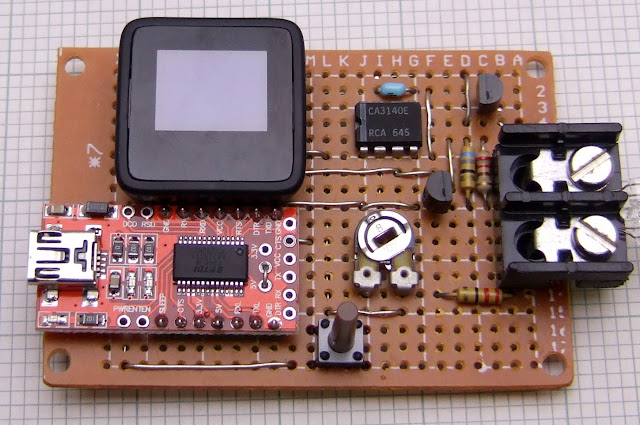
Here is the built up perfboard version. Note that this picture was taken before I added the offset null pot.


Here is the underside :-


I made a 3D printed case of course, using OpenSCAD. It was a great help that there was a 3D model of the MicroView case parts available in STL format. I was able to assemble them to make an accurate 3D representation of it and also use it to cut the hole in the case lid. Once I had measured up the perfboard I was able to locate all the components that needed holes in the case by using their grid coordinates. Amazingly this was right the first time I printed it.


I used HEATFIT brass threaded inserts which I pushed in using a soldering iron with a conical bit.


Here it is assembled and running. Unfortunately the camera shutter missed the most important bits of the text, the temperature and power.


The cheap perfboard I used was a bit warped so the board is sandwiched between the top and the base, supported all around its edges top and bottom, and clamped with four screws. The screw heads are recessed into the base so that it sits flat.

When I was following instructions to install the MicroView bootstrap I discovered CodeBender. This allows you to store an Arduino project in the cloud, edit it in a web page, compile it in the cloud and download into an Arduino using a web browser plug in. It's much more convenient than installing hundreds of megabytes of Arduino IDE and the editor is much nicer. Here is the actual code: Click on the title to see a non-embedded version in its own webpage.

The MicroView doesn't have any separation between the analogue and digital power rails so I guessed the ADC readings would be quite noisy. I knew that the AVR can be made to sleep while the ADC is sampling to reduce the amount of digital noise. I scraped some code from the Arduino forum to do that. Ten bits is not a lot of resolution so I do 16 reads in quick succession and add them together to get a 16 bit result. In the presence of random noise oversampling can increase the resolution at the expense of the sample rate. Marlin firmware uses this technique for reading temperatures.

The ADC uses the 5V rail for its reference but the actual voltage at the end of a USB cable is somewhat unknown, so I measure the internal bandgap reference to calibrate the other two voltage readings.

Once the glass is removed from the bulb the voltage becomes quite unstable. I think this is because of chaotic air turbulence. I first noticed this effect when using a thermocouple to measure the temperature at the surface of a heated bed. The control loop might be somewhat unstable due to it having a high gain and bandwidth controlling a laggy heater. It may tend to over correct and overshoot. Despite this I found that averaging over 100 samples gave a stable reading.

The firmware displays the three voltages it measures (VCC, the bridge voltage and the bulb voltage) averaged over the last 100 samples. It also displays the calculated power and temperature of the bulb.

I adjust VR1 to set the temperature to 185°C to emulate freshly extruded filament. I don't think the exact temperature matters much. Making it higher increases the sensitivity but there may not be enough voltage to maintain it in a strong airflow. Also you probably don't want it glowing as it might oxidise. It takes a lot more power to reach a given temperature once the glass is removed, obviously, as you have convection cooling even in still air rather than just radiation.

Pressing the button causes it to subtract the current power level from subsequent readings. That is done in still air so that the power reading is then just the extra heat carried away by a moving airflow.

The serial protocol is minimal. If it receives z it zeros the power and replies ok. If it receives s it clears the sample buffer and replies ok. After it gets 100 samples it sends VCC, the bulb power and the bulb temperature.

As this article is long already I will show the results in another post. In the meantime here is a scan of the standard Mendel90 fan duct's cooling effect at 2mm resolution.


Thursday 28 January 2016

A bridge too far

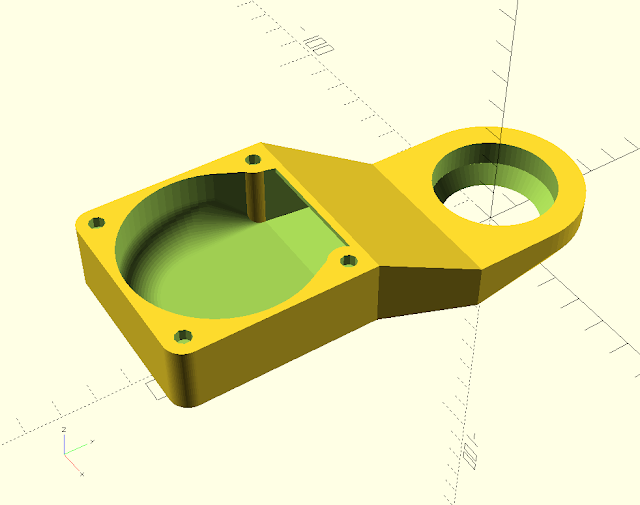
This version of the Mendel90 fan duct that accommodates the E3D V6 hot end happens to be a shape that is surprisingly difficult for slicers. It is because of the shallow sloping slanted bridge.


Skeinforge

I slice everything I print with Skeinforge, so the normal Mendel90 parts are designed around its limitations. It normally does a good job of detecting bridges and aligning the infill to span the gap. Its big limitation is that it does the infill for an entire layer in one direction, whereas it should at least be per island. However, even with the original flat fan duct it doesn't see the first layer of the roof as a bridge.


Left to its own devices it does this for the bridging layer.

Layer before roof: -


First bridging layer: -


Clearly this doesn't print well because the ends of the infill don't land on anything. The orange section of infill has nothing under the yellow internal edge, so the loops just fall down.

Filament runs can't start, end or change direction when there is nothing under them, whether it be infill or outline. I don't know what algorithms slicers use but if I was writing one I would generate the infill for an island at the default angle and then check that all the end points land on something below. If not then I would try aligning it with each of the straight sides of the outline, starting with the longest first, noting how many endpoints miss. In most cases that would yield a direction with no misses. In the unlikely event it didn't then I would go for the direction with least misses and try reducing them by tweaking the angle. If there is no solution then I would issue a warning and miss out the lines that can't be printed.

To get around Skeinforge not spotting the bridge I set the infill starting angle to 90° so that the first bridge layer happens to be in the right direction anyway.


This workaround is OK when you have just one layer that bridges. With multiple layers you might need to slice with different angles and then splice the gcode together, but that is getting very inconvenient.

I normally print Mendel90 parts with 0.4mm layers, but I print the duct with 0.35mm layers in order to stretch the filament tighter, so that it bridges the large gap with less droop. The fact that it isn't detected as a bridge means that special bridging settings can't be applied.

When it comes to the new duct this strategy doesn't work because every layer of the sloping bridge advances left with nothing underneath. So consecutive layers are all bridges at the left edge. With normal 90° infill rotation every second layer has its infill changing direction in mid air. It is supported a little way back, so only small loops hang down, but that makes the inside of the duct very ugly and can't be good for airflow. Also if I print it with 0.35mm layers then the extra tension makes it tend to curl upwards and brush the nozzle, leaving brown marks on the top surface.

I could set the infill rotation to zero so that every layer is the right direction for the bridge but that would lead to a weak object, especially where the infill is sparse, so I haven't tried it. What is needed is a slicer that can split the sloping roof layers into a left unsupported edge that is printed as a bridge and the rest that is printed with normal diagonal infill. I know that other slicers can have different infill patterns within one island, so I decided to try them out with this object.

Cura 15.04.3

Cura seems to display infill as solid yellow in its layers view, so I used gcode.ws to display the gcode.

Cura doesn't detect a bridge and just uses diagonal infill all the way. Interestingly it doesn't connect the ends of the infill, it does a short move at high speed with no retraction. Also it doesn't seem to have any retraction when it moves significant distances across the infill. This is one of the reasons I don't use Cura. I need retractions before all moves longer than say 1mm otherwise it leaves a trail behind and the next line doesn't start properly as there is missing plastic.

KISSlicer 1.1.0.14

KISSlicer shows some errors in the STL but the colour it uses to highlight them isn't in the key, so I don't know what it thinks is wrong. There are no errors in Netfabb Basic so I am pretty sure the file is OK.


It too doesn't recognise the bridge and just does normal diagonal infill over it, using a colour scheme that is very difficult to see!


One odd thing is seems to do is inset the internal walls a little further on the last layer below this one, perhaps to give the infill more area to land on.

Slic3r 1.2.9

Slic3r actually detects it as a bridge but gets the angle slightly wrong.

Two infill lines start or end in mid air. I discovered though that if I rotate it 90° the infill comes out correct.

This is a shame because I orientate it length ways for printing. That is because on a moving bed Y axis you want to minimise the Y movement to keep the object in warm air.

The next layer does exactly what I want. I.e. it does horizontal infill where there is nothing underneath but reverts to normal diagonal infill where there is something below.

So far so good but after a few more similar layers it starts to go a bit wrong.

It gets the boundaries of the bridge region wrong. It has a few lines of infill turning in mid air at the right hand side. Further up the slope it gets the left hand side wrong as well. I suspect it is because the slope slants left to right.

Further up it gets a bit more strange.

I haven't tried printing it but I suspect it would come out not too badly, with just a few small loops hanging down. At least it does logically the right thing, shame about the bugs in getting the bridge angle and region accurate.

CraftWare 1.13 beta

This is a late addition suggested in the comments. Perhaps the nicest user interface of all but it doesn't detect bridges at all in this object.


Simplify3D 3.0.2

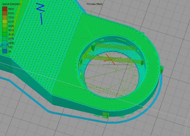
Since none of the free slicers I know of got this right I decided to try a paid for one. With a single outline it fails to detect the first bridge and just does diagonal infill in mid air.


On subsequent layers it does seem to divide the layer correctly into a bridge region and a normal region but gets the infill direction in the bridge area completely wrong.


With two outlines it gets the main bridge correct but the slope now doesn't have a separate bridge region, just diagonal infill. That is except for just one layer and that also has the direction wrong.


 The odd layer corresponds with the solid support diaphragms over the screw holes.


This does print slightly better than the Skeinforge one but only because the extra outline means the infill lines don't need to overhang quite as far.

Conclusion

So in summary I can't find a slicer that gets this correct but Slic3r is the closest. Of course they all offer support material but that would be difficult to remove inside the duct and there in lies another raft of bugs, if you pardon the pun. See below: -