
Skeinforge
I slice everything I print with Skeinforge, so the normal Mendel90 parts are designed around its limitations. It normally does a good job of detecting bridges and aligning the infill to span the gap. Its big limitation is that it does the infill for an entire layer in one direction, whereas it should at least be per island. However, even with the original flat fan duct it doesn't see the first layer of the roof as a bridge.
Left to its own devices it does this for the bridging layer.
Layer before roof: -

First bridging layer: -

Clearly this doesn't print well because the ends of the infill don't land on anything. The orange section of infill has nothing under the yellow internal edge, so the loops just fall down.
Filament runs can't start, end or change direction when there is nothing under them, whether it be infill or outline. I don't know what algorithms slicers use but if I was writing one I would generate the infill for an island at the default angle and then check that all the end points land on something below. If not then I would try aligning it with each of the straight sides of the outline, starting with the longest first, noting how many endpoints miss. In most cases that would yield a direction with no misses. In the unlikely event it didn't then I would go for the direction with least misses and try reducing them by tweaking the angle. If there is no solution then I would issue a warning and miss out the lines that can't be printed.
To get around Skeinforge not spotting the bridge I set the infill starting angle to 90° so that the first bridge layer happens to be in the right direction anyway.

This workaround is OK when you have just one layer that bridges. With multiple layers you might need to slice with different angles and then splice the gcode together, but that is getting very inconvenient.
I normally print Mendel90 parts with 0.4mm layers, but I print the duct with 0.35mm layers in order to stretch the filament tighter, so that it bridges the large gap with less droop. The fact that it isn't detected as a bridge means that special bridging settings can't be applied.
When it comes to the new duct this strategy doesn't work because every layer of the sloping bridge advances left with nothing underneath. So consecutive layers are all bridges at the left edge. With normal 90° infill rotation every second layer has its infill changing direction in mid air. It is supported a little way back, so only small loops hang down, but that makes the inside of the duct very ugly and can't be good for airflow. Also if I print it with 0.35mm layers then the extra tension makes it tend to curl upwards and brush the nozzle, leaving brown marks on the top surface.
I could set the infill rotation to zero so that every layer is the right direction for the bridge but that would lead to a weak object, especially where the infill is sparse, so I haven't tried it. What is needed is a slicer that can split the sloping roof layers into a left unsupported edge that is printed as a bridge and the rest that is printed with normal diagonal infill. I know that other slicers can have different infill patterns within one island, so I decided to try them out with this object.
Cura 15.04.3
Cura seems to display infill as solid yellow in its layers view, so I used gcode.ws to display the gcode.
KISSlicer 1.1.0.14
KISSlicer shows some errors in the STL but the colour it uses to highlight them isn't in the key, so I don't know what it thinks is wrong. There are no errors in Netfabb Basic so I am pretty sure the file is OK.
It too doesn't recognise the bridge and just does normal diagonal infill over it, using a colour scheme that is very difficult to see!

One odd thing is seems to do is inset the internal walls a little further on the last layer below this one, perhaps to give the infill more area to land on.
Slic3r 1.2.9
Slic3r actually detects it as a bridge but gets the angle slightly wrong.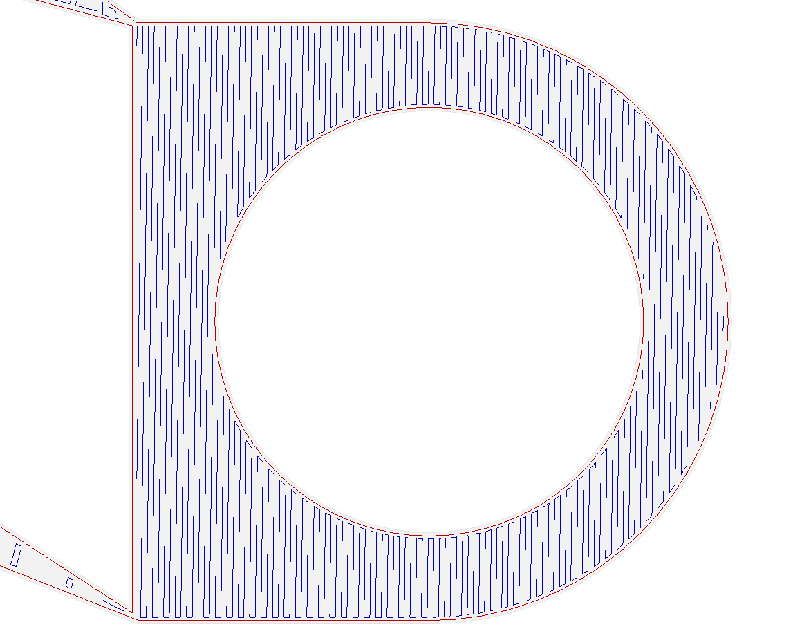

The next layer does exactly what I want. I.e. it does horizontal infill where there is nothing underneath but reverts to normal diagonal infill where there is something below.


CraftWare 1.13 beta
This is a late addition suggested in the comments. Perhaps the nicest user interface of all but it doesn't detect bridges at all in this object.
Simplify3D 3.0.2
Since none of the free slicers I know of got this right I decided to try a paid for one. With a single outline it fails to detect the first bridge and just does diagonal infill in mid air.
On subsequent layers it does seem to divide the layer correctly into a bridge region and a normal region but gets the infill direction in the bridge area completely wrong.

With two outlines it gets the main bridge correct but the slope now doesn't have a separate bridge region, just diagonal infill. That is except for just one layer and that also has the direction wrong.

The odd layer corresponds with the solid support diaphragms over the screw holes.

This does print slightly better than the Skeinforge one but only because the extra outline means the infill lines don't need to overhang quite as far.
Conclusion
So in summary I can't find a slicer that gets this correct but Slic3r is the closest. Of course they all offer support material but that would be difficult to remove inside the duct and there in lies another raft of bugs, if you pardon the pun. See below: -


Just found out about this one myself, but does CraftWare produce any different results? https://craftunique.com/craftware
ReplyDeleteI have added CraftWare, thanks for pointing it out. It too doesn't do bridges.
DeleteIn Cura you can disable combing to force retractions between infill lines. Cura does have code to decide on the direction of the top/bottom skin to get better bridging (per skin area), but I haven't tested bridging in quite some while.
ReplyDeleteIt's difficult for me to understand where you would like good bridging. Can you maybe attach a link to the model?
Hi Tim,
DeleteThanks for the tip about retraction.
The model is here: https://github.com/nophead/Mendel90/blob/master/dibond_E3D/stls/x_carriage_fan_duct.stl.
The ideal bridging is as Slic3r does but without the numerical errors. I.e. the first layer over the rounded end should always be exactly parallel to the unsupported edge so that no infill lines start, end or turn on that edge.
On the sloping surface the unsupported infill should again always be parallel to the unsupported edge. The area of the bridge should extend right to the outside edges, not stop short.
A slicer should never output paths that start, end or turn in mid air. Cura does that all over the place because it fills arbitrary areas on top of sparse infill. Skeinforge always fills to the edge and it always connects the ends of the infill at the edge. That means there is effectively a second skin for free and also gives something to support the infill ends of the layer above. Unsupported infill ends curl up and burn on the nozzle making unsightly brown marks on the prints.
Also you can connect the end pieces of the infill lines by selecting zigzag as infill pattern in the new Cura, though I am convinced that the lines pattern is better.
ReplyDeleteThis is a great idea to have around if you want to test shroud designs. I design and test shrouds, but test them by printing small objects and overhangs and this is far from accuracy desired. If you are willing and able to test one of my models, I would appreciate it very much. https://www.youmagine.com/designs/e3d-v6-30mm-clip-on-fan-shroud
ReplyDeleteWe at Prusa3D are investing into the internal development of Slic3r, so I can explain both the issues with the Slic3r bridging algorithm.
ReplyDeleteFirst the bridge orientation is calculated by testing various discrete orientations and picking the best. So this explains why the infill line is not aligned with the edge.
Second, the infill on higher layers does not span the region because there is a "top" surface detected, which takes precedence. The "top" surface is any surface visible from the top and Slic3r by default extends the "top" surface region by 3mm to anchor it inside the object. This is not an optimal solution in many cases.
By the way, Richard, thanks for the design of the cool meter, I have built one for our purposes.
Thanks for the insights.
ReplyDeleteBTW, my name is Chris, not Richard.
Hello Chris!
ReplyDeleteThis project looks amazing! Did you have any interest in testing my part cooler design made and simulated in Solidworks?
https://groups.google.com/forum/#!topic/deltabot/ElN27Em78s4
There are STL file and making history, if needed i can try adopt it to any configuration. I will be happy to see it tested in real life with your setup.
Cheers!