Thursday 21 January 2016

Mendel90 GitHub catch up

I finally found time to update GitHub with some Mendel90 changes that I have had in the works for a long time. The problem with releasing them sooner was that they were all not quite finished and / or would make unintended knock on changes to the kits I was producing. In particular the changes I did to make a Huxley90 in a hurry for the TCT show and the E3D mods kindly contributed by Philippe LUC that conflicted greatly with it, so needed a lot of work to merge.

OpenScad

I also updated to the latest version of OpenScad. The upside was that hull and some of the 2D operations are much faster. I was also able to replace all the calls to minkowski with offset as I was only using it for 2D offsetting. The net result is it is now four or five times quicker to generate the preview and the STL files. The downside is that the 2D sub-system now uses fixed point coordinates but the rest of OpenScad doesn't. This makes it difficult to get 2D and 3D geometry to match up. For example, an extruded circle now has slightly different vertices to a cylinder of the same size. This created a few degenerate triangles requiring that I changed the way I constructed some objects in order to get nice clean STL files.


The solution in the case above was to make the cylinder slightly bigger than the circle used to make the pointer.

On the up side it seems OpenScad has got better at handling unioning exactly coincident faces since I first wrote Mendel90, so I could remove some of my small offset bodges to avoid z-fighting.

Another benefit is that the X end brackets now slice correctly in Slic3r, as the bug that caused internal faces to point the wrong way has now been fixed. Skeinforge doesn't care about face orientation, it just counts edges to work out what is inside and what is outside. Other slicers got confused and filled in the nut cavity.


Along the way I discovered that, although OpenScad now has trig functions that are accurate for multiples of 90 degrees, etc., it doesn't use them in rotate, or vertex creation for circles and cylinders. It converts to radians and uses the library trig functions. Degrees can never be represented accurately as radians in floating point because Pi is irrational, not to mention transcendental. To get round this I now override the built in rotate with a user space version that uses the accurate sin and cos degree functions.

module rotate(a)
{
 cx = cos(a[0]);
 cy = cos(a[1]);
 cz = cos(a[2]);
 sx = sin(a[0]);
 sy = sin(a[1]);
 sz = sin(a[2]);
 multmatrix([
  [ cy * cz, cz * sx * sy - cx * sz, cx * cz * sy + sx * sz, 0],
  [ cy * sz, cx * cz + sx * sy * sz,-cz * sx + cx * sy * sz, 0],
  [-sy,      cy * sx,                cx * cy,                0],
  [ 0,       0,                      0,                      1]
 ]) children();
} 

Not surprisingly every STL and DXF file generated is now slightly different numerically but hopefully not dimensionally. I made a stable branch to record the state before these global changes, just in case. GitHub has some excellent image and STL comparison views but unfortunately it gives up if more than a handful of files have changed and there are hundreds in the Mendel90 tree.

Wade's Block

After a few people started to report broken or cracked Wade's blocks I strengthened it a bit around the bearing block. I also made the bearing sockets a bit bigger so there is less stress created pressing them in. Kits from around March 2015 have shipped with this version.

X Carriage

When Philippe LUC created the E3D branch he fixed a few bugs. One of these was that the X carriage top was only 2mm thick, when the design intent was 3mm. This was due to the fan duct using the same variable name. Whoops! I have updated it now in the main branch. I also made the nut traps for the fan bracket screws deeper to allow for longer screws and to allow them to be withdrawn further without loosing the nuts. This makes it easier to remove and replace the duct. Simply removing the washers is an alternative.

E3D Hotend

I temporarily parked Philipp's mods in an E3D branch until I could merge them. I have now updated the master branch to support E3D V5 and V6 hot ends with this one line change to the config file. The generated files for V6 that are different from standard build are in new folders dibond_E3D and sturdy_E3D and I have deleted the temporary E3D branch.


There is no room for the right hand wing nut because it clashes with the hot end's fan. Fortunately the carriage has always had nut traps to allow the screws to be inserted from below. A plain nut above can then be used to secure the extruder.

Primarily the things that change are the Wade's block, the fan duct and the fan bracket. The Wade's block has no extension to avoid losing more Z build height than necessary and a plain screw hole on the right end instead of the hex socket.


The fan duct has to slope downwards to avoid the E3D heatsink. That creates a sloping bridge that is also skewed horizontally. I haven't found a slicer that handles this properly yet, having tried Skeinforge, Slic3r, Cura, Kisslicer and even paid for Simplify3D! I have blogged about their failings in another post here: hydraraptor.blogspot.co.uk/2016/01/a-bridge-too-far. Any other slicers I should try?


Another bug Philippe noticed is that there was almost no clearance between the fan and the belt. Fortunately the belt is twisted so it actually does clear the fan. I have added more clearance as
Philippe did. It makes the fan bracket and fan duct 2mm longer. If you print either from the new files be sure to print both or the duct will be misaligned.

I also improved the internal shape of the duct a bit. From this: -


To this: -


It probably doesn't make a lot of difference but a comparative test of various fans and ducts will be the subject of a later post.

Even with the shortened Wade's block the E3D V6 hot end is 4mm lower and the V5 is a bit longer still. If you retro fit it to an old machine you will lose 4mm Z travel. If you are building a new machine then there are alternative files which add 4mm to the height of the frame and lengthen the Z smooth rods and threaded rods on the bom. That also has a knock on effect on the shape of the spool holders and the dust filter. If you use the larger sheets be sure to get the correct size rods and use the correct spool holder parts to match the frame.

New Lighting Options

I redesigned the lighting system I described here to work with some commonly available LED light strips. These consist of an aluminium PCB strip that slides into an aluminium extrusion with plastic end caps, which I discard. Instead of printing a bar to hang the lights and camera from I now add printed end caps to the light strip and uses those to hinge it from the frame edge clips. I then hang the camera from the strip with its own hinge.


The strips come in 500mm lengths but they can be cut at discrete points between every third LED. They are described as "50CM 5050 SMD 36 LED Warm White Aluminium Rigid Strip Bar Light Lamp" and I bought them from bgood2010 on eBay.


I got some from another seller and although the eBay picture looked the same the extrusions where actually not as deep. The STL files on GitHub are for 8.6mm deep extrusions and are generated by light_strip = RIGID5050_290. Setting it to Rigid5050_290 generates the clips for 7mm deep extrusion. Other sizes can easily be accommodated as long as they are rectangular. The definitions are here.

Rather than waste the off-cut I mount it above with a second pair of end caps that clip onto the main light strip. These are set back just far enough to avoid the build volume in the unlikely event you print something tall at the back edge of the bed. This is calculated by the model with lots of trig and Pythagoras maths. Set show_rays = true to see this view showing that the camera and lights are pointing at the centre of the bed and the build volume is clear.


Another light strip that can be selected is this one: FSRP3W, discovered by Alzibiff.


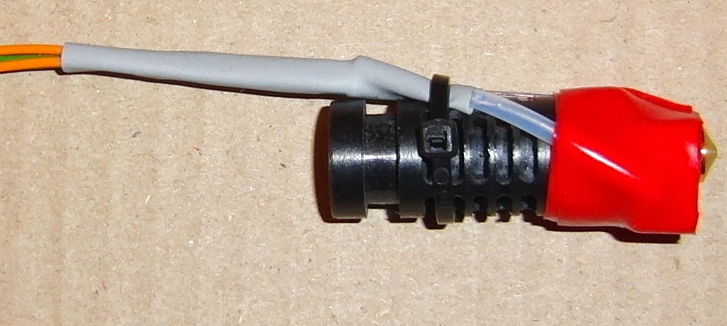
Again the end caps are removed and replaced with printed ones that clip into the screw channels in the extrusion. There is no room for the plug so I just solder the wires on.


It looks neater and gives a more diffuse light but is not as bright as the double strip of 5050 LEDs and is more expensive. I bought it from www.ledlightingandlights.com.

The only problem with these light strips compared to my original Sanken ones is that they are unregulated, so they flicker when the bed switches on and off. I described how I fixed that here. I also need to update the mounting for the Raspberry Pi to accommodate the plethora of new Pis that have appeared since my original design.

Huxley90

The Huxley version is scaled down in the same way as the Sells Mendel was scaled to make the Huxley. It has a build volume of 150mm cubed and uses NEMA14 motors, 6mm smooth rods and M3 fasteners for the frame. There is a good photo of it alongside the full sized machine on Ivor O'Shea's blog post.

The NEMA14 motors have about half the torque of the NEMA17s when driven with the same current. The Y carriage and bed have about half the area hence half the mass, so that is about right. Also a NEMA14 has half the mass of a NEMA17, so the X carriage also has about half the mass.

I believe the flex in the middle of the rods is proportional to the length cubed times the weight divided by the bar radius to the power of four. The length of the X rods is almost exactly 75% of the Dibond version and the diameter is obviously 75% as well. The relative flex then boils down to 0.5 / 0.75 = 0.67. So going down to 6mm rods is justifiable as well. Everything scales very nicely physics wise.


As the design is fully parametric shrinking it should have been easy, but because vitamins don't scale perfectly lots of snags arose where things clashed. A typical example was the x_motor_bracket. The NEMA14 motors are smaller but the raised boss around the shaft is the same size. This makes the bracket a different shape and it then needs a support to print it.


Half a truncated teardrop with a crutch!

The heated bed was made with veroboard and coincidentally has the same resistance as a full sized Prusa PCB, so the machine takes the same amount of power but heats up about twice as fast. There is no room on the frame for an ATX PSU, so I used an external XBOX 200W PSU. I couldn't find a spec for the 5V standby rail but it seems to supply enough current to power a Raspberry Pi.

Direct Drive Extruder

The extruder is where the scaling fell down a bit. The original Huxley used a Bowden drive to make the carriage small. I didn't fancy that but I didn't want to have the carriage as big as a geared extruder would need, so I went for direct drive with a NEMA14 and 1.75mm filament. 


The filament needs about one third of the force to feed and a Wade's has roughly 1:3 gearing, so a direct drive NEMA17 is about equivalent. The NEMA14 has half of the torque, so it is a bit under powered. I used the smallest drive pulley I had which was a mini hyena from Laszlo Krekacs' Indigogo campaign. Unfortunately I don't think the small diameter version is available now. I could probably make one from a hobbed bolt if I needed to or hob one from scratch.

It feeds PLA fine at 200C but isn't able to pull it off a spool. I will try a spool holder with a central bearing rather than the rim bearings to see if that is low enough friction. If that doesn't work I might try a powered filament supplier like the one on the first Up printer preserved here. Or maybe even try Bowden drive.

The design is parametric so there is a NEMA17 version suitable for Mendel90. I just need to adapt it for a commonly available drive pulley. It should just be a matter of adding a description here.

It can also use the E3D hot end but that doesn't fit between the bars on a Huxley90.


So that is Github up to date and hopefully correct although I haven't tested a lot of these changes.

I noticed that Blogger is now a lot worse than it used to be. Headings and pictures are now a nightmare.

Tuesday 6 October 2015

End Game

Since my last post there have been many expressions of sadness in the comments here and here. I'd be lucky to get so much mourning at my funeral I think! Yes it may be sad for potential customers that missed out, but not for us. Fortunately we are at a stage in life where time is more important than money to us. It does feel a bit weird though as the house is now silent after having three or four machines printing solidly for about five years.

The harsh reality is we always planned to stop selling kits before demand dried up completely because otherwise we would be left with unsold stock. In order to to get volume discounts and cover long lead times we needed to carry around £12,000 - 15,000 of stock.

As we didn't hire premises or staff, and had enough capital to cover cash flow, the only business risk we had was being left with stock. It was very hard to predict future demand because it fluctuates wildly with currency changes and, with a new 3D printer coming out nearly every day, there is a risk sales could suddenly dry up if a better cheaper kit emerged. For example, a £40 Prusa I3 from China with 2 rolls of filament and LCD, bargain!

In the end the issue with Dibond made the tricky decision of when to stop for us. This happened a few months ago and we synchronised most of our stock to all run out together.

Yes we could have used other sheet materials, solid aluminium and steel were suggested. However, these are more expensive to buy and machine, much heavier and therefore more costly to ship. Although they are a bit stiffer there is no real advantage to the frame being stiffer because the forces due to accelerating the axes is along the plane of the sheets, where almost any sheet is very stiff indeed. As long as the machine sits on a solid work surface it doesn't flex at all when printing, unlike some of the triangular prism machines.

The good thing about an Open Source product is that the design and instructions will always be available, so people can still self source, or another company could pick up the baton. We will always be able to supply printed parts and, fastener kits, wire and sleeving, hobbed bolts and the extruder PCB. See the RepRap forum for prices. Everything else can be self sourced.

Friday 2 October 2015

No More Mendel90 kits

We sold our last Mendel90 kit today. We found it increasingly difficult to get Dibond that wasn't scratched and after going through four different suppliers we eventually gave up and synchronised the rest of our stock to the number of good Dibond sheets we had managed to get.

The problem is we don't have room for an 8' x 4' router, so we get the sheets cut into smaller blanks that fit on my A2 router. The sawyers that cut them keep forgetting that, unlike other materials like wood and acrylic, the aluminium chips that come off Dibond are sharp enough to cut through the protective film and damage the surface. That means that all the chips need to be cleaned off the cut pieces before they are stacked. You would think that companies whose main business is selling cut to size sheets for decorative use would know this, but they all seem to make the same mistakes over and over again, wasting my time and their money.

Many thanks to all our customers for all their kind words and recommendations.

Back to experimenting and blogging ...


Wednesday 30 July 2014

PLA pipe cleaner

Yesterday one of my machines stopped extruding ABS mid print. I immediately suspected the filament as faulty filament is my main source of unreliability these days, having eliminated other things like push fit connectors and wires that break.

I removed the hobbed bolt to clean it and found that I could not feed filament forward by hand but I could pull it back easily, a sign that the nozzle aperture was blocked by something. I spent a long time trying to clear the blockage with several attempts that failed. Here is the method that successfully cleared it in the end: -

I pushed the shank of a 0.4mm drill up the nozzle aperture while it was hot. That cleared the blockage enough to be able to extrude but the particle of contamination kept finding its way back into the aperture causing the plastic to come out in a flat turbulent ribbon instead of a cylinder. That made poor prints with rough surfaces and strings.

PLA has a useful property that you can heat it to a temperature between its glass transition and its melting point where it becomes a rubbery solid. When you pull it backwards it stretches and becomes thinner, so it peels away from the walls of the melt chamber and comes out in one piece. Anything in the melt chamber is pulled out with it leaving it completely empty and clean.

ABS does not have this property and is more like chewing gum above 105°C. It can be pulled back at around 130°C but it usually does not all come out because it is a super viscous liquid rather than an elastic solid.


Because of this I decided to flush out the ABS with some natural PLA. I did this at 240°C until it was extruding clear PLA,. then I cooled it to 80°C and pulled it out. This is how it looked: -


As you can see it stretches until the last bit comes away from the walls of the barrel and the shape of the end matches the cone leading to the nozzle. The problem is this did not get the particle blocking the nozzle because that was pressed into the aperture by the flow of PLA when I inserted it.

The final trick was to push a drill shank up the nozzle to force the contamination into the melt chamber before cooling it to 80°C. That ensured it was embedded in the PLA when I pulled it out. Here you can see the particle that caused all the trouble.


So to recap:
  1. Heat to extrusion temperature and pull out the filament being used.
  2. Use a 0.4mm drill shank to clear the aperture.
  3. Insert PLA (preferably natural so you can see the contamination) and flush through the remaining original filament. You may need to keep clearing the aperture with the drill shank.
  4. Cool the extruder to 80°C with the drill shank in place to ensure the nozzle is clear.
  5. Remove the drill and then pull out the PLA.
  6. Inspect the end that comes out to see the culprit contamination.
Of course if you are using PLA you can just do steps 4 and 5.

This method of cleaning with PLA is much better than using solvents or burning out nozzles that I often see recommended as it can be done in situ and doesn't risk damaging anything.

Friday 13 June 2014

Lights, camera, action ...

I have been using the excellent OctoPrint by Gina Häußge to control two of my Mendel90 printers with a Raspberry Pi for a while now. I prefer the convenience of using an Ethernet connection rather than USB. It means I can control a machine from any PC in the house rather than having to dedicate a laptop that had to be close to a machine. Here are the details of my set up: -

Mounting

There are several places a Raspberry PI can be mounted but I chose to place it on top of the PSU so that the wiring was kept short and didn't need to pass though any of the frame elements or need any new holes drilling. I.e. all the electronics are together in one bay.


I made a tray that supports the PCB all the way round and has a couple of pillars with M2.5 nut traps to screw it down. It shares the screws with the bottom of the Melzi, replacing the spacers, which are moved to the top.

raspberry_pi_assembly:
Vitamins:
  2 Nyloc nut M2.5
  2 M2.5 pan screw x 12mm
  1 Raspberry PI model B
  2 Washer M2.5 x 5.9mm x 0.5mm

Printed:
  1 rpi_bracket.stl
When it comes to mounting the camera there are again lots of possibilities. I contemplated something like this:http://www.shapedo.com/danielbull/raspberry_pi_camera_mount_for_the_nop_head_mendel90_3d_printer but I went for a straight on view from the back by printing a bar that spans the stays and clamps to the Dibond.


This gives a view orthogonal and centred with the bed so the only degree of freedom the camera needs is vertical tilt.


The bar can be clamped at any height. Lower gives a better view of the nozzle when it it close to the bed but tall objects soon go out of the field of view. Obviously a longer flat cable is needed to connect the camera to the RPI than the one supplied with it. They are readily available on eBay.

I also attached a 300 lumen LED light strip to the bar which gives enough light for the camera, even in a dark room. Having the light behind the camera avoids any glare from the glass. The particular strip I used is a SPS125 from Sanken Power Systems. I bought them several years ago and I don't think they are commonly available. However, the design is easily customisable by adding a new description to scad/vitamins/light_strips.scad. The clamps should then morph to suit.

The bar is printed in two unequal halves and the shorter one (red) slides into the longer one. The seam marks where the camera should be placed for alignment with the bed and the overlap length is such that both halves are the same height in total, so printing them together allows better cooling without needing excessive slowdown.

raspberry_pi_camera_assembly:
Vitamins:
  2 M2 cap screw x 12mm
  2 M3 cap screw x 10mm
  7 M3 cap screw x 16mm
  2 Nyloc nut M2
  9 Nyloc nut M3
  1 Raspberry PI camera
  1 Sanken SPS125 light strip
  2 Washer M2 x 5mm x 0.3mm
  9 Washer M3 x 7mm x 0.5mm

Printed:
  1 rpi_camera_bar_stl.stl
  1 rpi_camera_back.stl
  1 rpi_camera_focus_ring.stl
  1 rpi_camera_front.stl
  2 rpi_light_clamp.stl
By default the RPI camera is focused at infinity and the lens is locked in place. It is possible to break the seal though and focus it very close indeed giving a microscopic view. For this application it only needs tweaking a little to focus at the middle of the bed. I designed a little focus wheel that can be glued onto the end of the lens carrier to make it easier to turn.

When I ran the camera with the default settings in OctoPrint it streamed data at about 16Mbits / second and used 40% of the RPI's CPU time. It worked fine printing from SD card but slowed down the comms when printing over USB. On a suggestion by Gina I added the usestills option to scripts/webcamDeamon, i.e.
camera_raspi_options="-fps 10 -x 640 -y 480 -usestills"
That reduced the data rate to 3Mbps and the CPU load to 5%. It also had the side effect of vastly increasing the field of view. Here is a time-lapse captured by OctoPrint before I made the change. Notice the reduced field of view compared to the picture above.


Nothing on my WinXP machine would play the mpg files produced by OctoPrint, so I downloaded VLC Media Player. I found that is also able to record the OctoPrint video stream on the host PC. This video clip was recorded during the same build as the time-lapse above.


On another Mendel90 that I only use to print ABS parts, and hence don't fit the fan duct, I use a Logitech C270 USB webcam mounted in front of the machine, which gives a view like this: -


For this machine I mounted the same light strip just behind the gantry on brackets that hang over the top of the stays in the same way as the spool holders.


light_strip_assembly:
Vitamins:
  2 M3 cap screw x 10mm
  2 Nyloc nut M3
  1 Sanken SPS125 light strip
  2 Washer M3 x 7mm x 0.5mm

Printed:
  1 light_strip_bracket_left.stl
  1 light_strip_bracket_right.stl
I prefer the  RPI camera at the back solution but it does have the disadvantage that it looks out into the room rather than at the wall behind the machine.

Wiring

I power the RPI with the 5V standby rail of the ATX PSU and use one of the GPIO lines to turn the rest of the PSU on and off and another to turn the light on and off.

One thing I don't like about the RPI is the use of a micro USB connector for the power. A lot of micro USB leads have two much resistance to have enough voltage left at the RPI end. When you buy them there no indication of resistance but I managed to get some that where about 1.6Ω! To get around that I simply cut the wire off close to the plug and soldered to what was left.

The 5V volt supply comes from the purple wire of the ATX power supply. It looks blue on the photo below, but that is the camera lying! For a solid ground referenced to the logic on the Melzi I run a stout wire to the top terminal of the X limit switch. This ensures any voltage drop or noise in the ground wire between the PSU and the Melzi does not affect the USB comms and I find them rock solid in this configuration.


The remaining connections are the green PS_ON of the power supply goes to the drain of a small SMT MOSFET mounted on the back of the vero board and the negative lead of the light strip goes to the drain of a larger MOSFET. The positive lead of the light strip goes to the FAN+ terminal on the Melzi.

To make the vero circuit I started by cutting the tracks in a few places and drilling out some holes to provide strain relief for the flying leads.


I wanted the board to mount vertically but I didn't have a right angle connector to hand. Since I only need a few pins from one row I surface mounted a through hole straight connector.

Here it is with the MOSFETs and wires added: -

The small MOSFET is a 2N7002L and the larger one is a PHT8N06LT, but almost any logic drive N-channel enhancement mode MOSFETs should work. Neither gets fully turned on at 3V but both easily pass the current required, which is only milliamps for the PS_ON signal and about half an Amp for the lights.

On another machine I just soldered the MOSFETS to the connector and used heatshrink sleeving for strain relief for the flying leads on the drains. Much quicker but a bit fragile.

Software

OctoPrint

There are two ways to get OctoPrint onto a Raspberry Pi. You can start with a Raspbian image such as this one and then add OctoPrint by following these instructions or you can get an image for the RPI with OctoPrint already installed (called OctoPi) from here. The first method needs more steps and gets you the latest version. The second method is simpler but it takes me several hours to download, unzip and copy the image onto the SD card, so the first method can be quicker if you already have Raspbian installed.

When the RPI is booted you should be able to connect to it with SSH client like Putty or Tera Term. The default host name is octopi, username: pi, password: raspberry. If your DHCP server does not register the host name with DNS then you can find its IP address with a free application called Advanced IP Scanner found here. A good tutorial can be found here.

The first thing I do when connected is run :-
sudo raspi-config
to expand the file system, set the time zone and change the host name, etc.

VNC

In order to be able to update the firmware I install the Arduino IDE and to run that I need a remote desktop so I installed TightVNC following the guide here.

Arduino IDE

I install Arduino 1.0.1with:
sudo apt-get install arduino
I then get a copy of Marlin from Github with:
git clone git://github.com/nophead/Marlin.git
I then move the Melzi board support package to the Arduino IDE installation with:
cd Marlin
sudo mv Marlin/Melzi /usr/share/arduino/hardware


The Arduino IDE is a bit slow and clunky running on a RPI over VNC but it does work. A lighter weight alternative is a package called ino that can compile and download Arduino applications from the command line. It still needs the Arduino IDE installation but avoids the need for VNC.

Installation should be as simple as:
sudo pip install ino
But that installs an out of date version that does not scan the hardware directory for additional board support packages, and so does not support Melzi. Instead I install it from source:
git clone git://github.com/amperka/ino.git
cd ino
sudo pip install -r requirements.txt
sudo make install
If make install complains python2 does not exist then do:
sudo ln -s /usr/bin/python2.7 /usr/bin/python2
Ino expects the source code to be in a directory called src whereas the IDE puts it in a directory with the same name as the sketch. A simple workaround is to make a symbolic link in the directory above with:
ln -s Marlin src
rm -rf src/Gen7 src/Sanguino
(The other BSP packages have to be removed from the src directory because otherwise ino tries to build them and fails).

The firmware can then be built and downloaded with:
ino build -m atmega1284 && ino upload -p /dev/ttyUSB0 -m atmega1284

GPIO

To control the RPI's GPIO pins I followed the instructions here: https://projects.drogon.net/raspberry-pi/wiringpi/download-and-install/. This boiled down to:
git clone git://git.drogon.net/wiringPi
cd wiringPi
./build
Then I extended the systems actions section of ~/.octoprint/config.yaml with the following:
  - action: printer on
    command: gpio mode 5 out; gpio mode 6 out; gpio write 6 1
    name: Printer On
  - action: printer off
    command: gpio write 6 0
    confirm: You are about to turn the printer off.
    name: Printer Off
  - action: light on
    command: gpio mode 5 out; gpio write 5 1
    name: Light On
  - action: light off
    command: gpio write 5 0
    name: Light Off
After a reboot the printers PSU and the light can be turned on and off from the OctoPrint system menu. Obviously the light will only come on if the PSU is on.

Files

I added a new Python script that makes the STL files and BOM files for a list of accessory assemblies:
accessories dibond|sturdy|mendel
The STL files can be found here: github.com/nophead/Mendel90/tree/master/dibond/stls/accessories and the parts lists here: github.com/nophead/Mendel90/tree/master/dibond/bom/accessories. I also generated the files for sturdy and mendel variants but I haven't tested those myself.

Monday 9 June 2014

Why slicers get the dimensions wrong

People using Slic3r often complain that holes come out too small, see forums.reprap.org. This blog post is in reply to the question here.

The issue is not just with round holes (which shrink for reasons I described here) but rectangular or hexagonal holes as well. I got my rectilinear dimensions correct with Skeinforge nearly three years ago and blogged the maths here. I now design exclusively in OpenScad using polyholes to get cylindrical holes the correct size as well.

I have tried Slic3r, Cura and Kisslicer but none of them print the Mendel90 calibration part the right size, so I have stuck with Skeinforge. It is looking a bit old now as Enrique seemed to stop developing it around the time people started saying "Slic3r is nicer", but at least it is stable and has very few bugs.

Looking at the G code produced by Slic3r and Cura, they both assume the extruded outlines have a rectangular cross section. I.e. if I work out the volume of plastic extruded from the E number and feedstock diameter and divide it by the length of the line then I get an area. This is equal to the layer height times the intended filament width and the outline is offset by half the intended filament width. The problem is the filament does not form a rectangle if the edges are not constrained. It forms a rectangle with semi circular ends due to surface tension. The actual width of an outline of a given area is therefore slightly more than it would be if it was a rectangle.
The cross sectional area of a filament with height h and width W is that of a circle with diameter h plus a rectangle of width (W - h) and height h. A = πh2/4 + h(W - h).

Solving for W gives W = A / h + h(1 - π/4).

But slicers output enough filament to fill the rectangle, so A = intended w × h. Substituting that value for A we get W = w + h(1 - π/4). So we have an additional width that is just a fixed multiple of the layer height.
I print a lot of things with 0.4mm layers, so the error is very significant. To fix it in Skeinforge I set the outline flow rate to be enough to fill the rounded rectangle, rather than the full rectangle. I achieve this by setting the "Perimeter Flow Rate Multiplier (ratio)" on the Speed tab. A value equal to the "Perimeter Feed Rate Multipler (ratio)" gives an area equal to the full rectangle. To correct for the fact that it is actually a rounded rectangle one has to multiply the feed rate by the ratio of the areas, which is 1 + (π/4 -1) h / w, a value which only depends on the w / h ratio.
As you can see, when the w / h ratio is high the reduction in flow rate necessary is only about 4%. I assume the reason a lot of people don't notice this is that they use a high w / h ratio and then calibrate a thin wall box, so that the flow rate is low enough to compensate without making the infill too sparse. I generally print with lower values of w / h and prefer to just put in numbers, rather than measure thin wall thickness.

An alternative way to compensate would be to keep the flow rate the same but offset the outline by W/2 instead of w/2. I.e. by an additional h(1 - π/4)/2.

If objects are printed with multiple outlines then the error appears much worse if the inner outlines are printed first working outwards (or the opposite for holes). Looking at the area of plastic this is not obvious mathematically because an additional area of plastic equal to w × h will extend the width by w, preserving the original error but not adding to it.

However, if you consider the practicalities of the process it is obvious that you can't squeeze viscous plastic into the infinitely sharp point under the overhang of the previous outline, particularly when the opposite edge is completely unconstrained. In practice I think you get something like this: -
The plastic that fails to fill the overhang causes the opposite edge to bulge a bit further and this effect then gives the cumulative error that I experience. I don't think the correction factor is easily calculated because it depends on the viscosity of the plastic as well as layer height, etc.

So if you want accurate dimensions and multiple outlines then do the outer perimeter first. For better seam hiding on objects where the dimensions don't matter do the inner perimeters first. I tend to print most things with one outline as you effectively get an extra one free with Skeinforge because it joins the ends of the infill, see hydraraptor.blogspot.co.uk/2008/04/python-beans-make-object.

Tuesday 11 March 2014

Buried nuts and hanging holes

I needed to make some M4 nuts that could be finger tightened but I didn't have room for a standard wing-nut, so I decided to embed nuts in a printed plastic knob. I knocked up a simple design in OpenScad :-


M4 nuts are nominally 3.2mm thick. I made the base and lid 2.4mm and sliced it with 0.4mm layers. That meant the top of the nut would be flush with a layer boundary at 5.6mm and I confirmed that the first covering layer was at 6.0mm in Skeinlayer. So I needed to pause the build before the start of the layer at Z=6.0 and insert the nuts.

I run my USB machines using Raspberry PIs and OctoPrint (so that all my machines are connected via Ethernet) and noticed a post by the author, Gina Häußge, that said OctoPrint interprets an M0 in the gcode as a pause command. The host stops sending gcode until you press the pause button to un-pause it again. I believe other hosts use @PAUSE to do the same thing.

So M0 is exactly what I needed. The only problem is that up until then I mistakenly thought M0 meant end of program and placed it at the end of the PLA profiles that I distribute. Fortunately the version of Marlin I use ignores it but if you want to use the latest version, or OctoPrint, then you need to remove it from end.gcode, otherwise either the host or the firmware will pause at the end of the print and wait for a button press. Harmless but a bit confusing.

So, armed with a new appreciation of what M0 is, I searched my gcode for the first instance of Z6.0 which looks like this:

F12000.0
G1 X-9.082 Y3.907 Z6.0 F12000.0
G1 X-5.457 Y-3.937 Z6.0 F12000.0
G1 X-7.05 Y-3.803 Z6.0 F12000.0
G1 X-11.486 Y-4.991 Z6.0 F12000.0
G1 X-13.721 Y-10.229 Z6.0 F12000.0
G1 F1800.0
G1 E1.0
G1 F12000.0
M101
G1 X-12.65 Y-10.848 Z6.0 F1837.1615 E0.036

What we have is a sequence of non-extruding moves followed by an un-retract and the first extrusion. The moves are the result of the comb module and not really relevant if we are restarting after a pause, so I removed all but the last move and inserted my pause code:

M104 S100
G1 Z6.0
G1 X-100 Y-100 F9000
M0
G1 X10.0 Y98.0 F9000
G1 Z0.05
M109 S250
G92 E0
G1 E3 F50
G1 E-1 F1200
G1 X40.0 F4000
G1 Z6.0 F9000

G1 X-13.721 Y-10.229 Z6.0 F12000.0
G1 F1800.0
G1 E1.0
G1 F12000.0
M101
G1 X-12.65 Y-10.848 Z6.0 F1837.1615 E0.036

I set the extruder temperature to 100°C to minimise ooze and stop it discolouring while waiting for me to insert the nuts. The bed is left on so the half printed objects don't detach. It then moves up to Z = 6.0 to clear the objects before going to X = -100, Y =-100. That moves the bed to the front and the extruder to the far right on a Mendel90, giving the best access to the partially printed objects. M0 then pauses the program.

I threaded the nuts onto a screw to insert them easily without touching the hot plastic. 


After pressing the pause button to make OctoPrint resume, the print head moves to the front of the bed to do another ooze free warmup. The only difference from the start of the print is it parks the nozzle 10mm further left to avoid the blob it has already made and it moves to Z = 6.0 before resuming the print.

This all worked very well except for a slight snag. ABS does not stick to steel, so when it extruded the circular holes on top of the nuts it made a bit of a mess.


Normally I would use a one layer support diaphragm when printing suspended holes and drill it out afterwards. In this case it can't be drilled because the nut is in the way, so I developed a method of printing holes in mid air. 

The last layer of the nut trap looks like this: 


You can't print a smaller hole on the next layer as the outline would be printed in mid air. The infill is also only attached at one end. After a few layers it does sort itself out but leaves a mess. However, what you can do is print two bridges over the large hole with a gap between them equal to the diameter of the small hole:


This is done by cutting out a one layer rectangle clipped to the hexagon. It is rotated to match the layer's infill direction because Skeinforge fails to detect it as a bridge, probably because the bridged area is tiny.

On the next layer we can bridge in the opposite direction and close down the hole to a square:


Two sides are supported by the edges of the rectangle below and the other two span the gap. 

On the next layer we can approximate the hole with an octagon. Four edges are coincident with the square and the other four span small gaps:


It is now a good enough approximation to a circle for such a small hole so it continues up to the top as an octagon. The resulting print is much neater:


The cavity for the nut is made by subtracting a shape like this: 


Here is the OpenScad code. It needs various functions from the Mendel90 source tree.

//
// Smaller alternative to a wingnut
//
include <conf config.scad>

module hanging_hole(or, ir, ofn = 0) {
    union() {
        intersection() {
            if(ofn)
                cylinder(r = or, h = 3 * layer_height, center = true, $fn = ofn);
            else
                poly_cylinder(r = or, h = 3 * layer_height, center = true);
            rotate([0, 0, 90])
                cube([2 * or + 1, 2 * ir, 2 * layer_height], center = true);
        }
        rotate([0, 0, 90])
            cube([ir * 2, ir * 2, 4 * layer_height + 4 * eta], center = true);

        rotate([0, 0, 22.5])
            translate([0, 0, 2 * layer_height])
                cylinder(r = corrected_radius(ir, 8), h = 100, $fn = 8);
    }
}

base_thickness = 2.4;
lid_thickness = 2.4;

function nut_knob_height(nut) = base_thickness + nut_thickness(nut) + lid_thickness;

module nut_knob_stl(screw = M4_hex_screw, d = 14) {
    nut = screw_nut(screw);
    h = nut_knob_height(nut);
    flutes = 3;

    stl("nut_knob");
    rotate([0, 0, -45])
        difference() {
            cylinder(r = d / 2, h = h);                                                 // basic shape

            for(i = [0 : flutes - 1])                                                   // flutes for finger grip
                rotate([0, 0, i * 360 / flutes + 30])
                    translate([d * cos(90 / flutes), 0, base_thickness])
                        cylinder(r = d / 2, h = 100);

            union() {                                                                   // nut cavity
                difference() {
                    translate([0, 0, base_thickness + nut_thickness(nut)])
                        nut_trap(screw_clearance_radius(screw), nut_radius(nut), nut_thickness(nut));

                    translate([0, 0, base_thickness + nut_thickness(nut)])              // remove top of nut trap
                        cylinder(r = 20, h = 110);
                }

                translate([0, 0, base_thickness + nut_thickness(nut)])
                    hanging_hole(nut_radius(nut), screw_clearance_radius(screw), 6);    // replace with hanging hole
            }

        }
}

So this seems to be a general solution to printing holes in mid air without any support material. The only downside is that it is a bit weaker than using a membrane and drilling it out. In this case no strength above the nut was required. In general you can just make it two layers thicker.

Saturday 5 October 2013

Mendel90 design improvements

I temporarily suspended kit production for a few weeks in order to have some time to make some improvements to the design. The following improvements apply to kits currently being shipped.

Hot End

It came to light during the hot summer that the top of the J-Head can get too hot for extruding PLA. The problem seems to manifest itself when extruding slowly because it takes longer for the filament to pass through the hex grub screw (which is the Achilles heel of the J-Head because it is wider than the rest of the filament path) and so has enough time to soften and buckle. Ironically it is also more of a problem when extruding at lower temperatures because the filament gets harder to push and so buckles at a lower temperature.

On investigation I found what I had suspected for a long time: that the heat at the top is mainly due to convection rather than conduction. This is easily demonstrated by running the extruder on its side. A lot of people add a second fan but a simple solution is to insulate the heater block. I now wrap it in two turns of silicone "self amalgamating" or "self fusing" tape, which is rated for 260°C. There are several brands but I use E-Z Fuse Tape which is 25mm wide. I stretch 110mm of it around the bottom of the PEEK, just below the bottom vent slots. I then trim it flush with the bottom of the heater block with a pair of scissors.


This makes enough difference to allow it to extrude very slowly without jamming. To cool it further I added a small hole to the fan duct.

A small airflow makes a big difference because it disrupts the convection but it is only active after the first layer when the fan is on.

It is possible to drill the hole to upgrade an old fan duct but straight drilling will spit the layers apart as it is a very thin wall. The way I did it was to melt a hole using a soldering iron with a conical bit set to 200°C. At that temperature you can wipe the ABS off the bit before it has chance to burn and make a mess of it. I then clean up the hole by drilling the melted ring it with a 4.5mm drill and then trim it flush with a penknife.

Another mod I made was to apply a bit more pressure to the idler by adding washers to each end of the springs. The same effect can be achieved by tightening the screws so they go about 1.5mm past the back of the bearing block but I like them flush with the block for an easier reference point.


These three little changes made a big difference and I can now extrude PLA at 185°C, which gives better print quality. I have updated the android gcode I include on the SD card and I have put the new Skeinforge settings on Github.

Settings

Other improvements I made to the settings are: -
The PLA settings were erroneously under the ABS profile, sorry for the confusion. The un-configured profiles have been removed and two new ones: PLA0.3 and PLA0.2 have been added. The android sample is sliced with the 0.3mm layer profile because it is easier to get the Z calibration right with the highest layer height possible with PLA. The 0.2mm profile gives a much nicer print.
The ooze free unattended start was not very reliable with PLA. Lowering the temperature helped but I also improved the extruder priming by extruding a very fat line along the front edge of the bed instead of a blob.
I have come to realise that you get better prints if you do the outlines at the same speed as the infill and looking back I think that is what I have seen commercial machines do. The old profiles had the outlines at 25mm/s and infill at 50mm/s. I now do both at 40mm/s.
The reason it works better is because when the extruder rewinds at the end of one run and then fast forwards the same distance to start another it will restore the same nozzle pressure as it had on the previous run. That means the initial flow rate will be the same, so if the speed has changed it will be too fast or too slow. This leads to blobs on the outline after doing faster infill and gaps at the start of infill after doing slow outlines. 
Another advantage is with a constant flow rate the plug of plastic that forms at the hot end transition zone will be a constant length. If the speed increases the length reduces, which means less of the barrel has plastic expanded to the barrel's diameter and more has it at the original filament diameter. This implies there is less plastic in the barrel, so an excess must have been extruded while the plug was shortening. Conversely when the extrusion rate drops the plug extends so too little plastic will be extruded during that time.
Yet another advantage of using constant flow rate is that the die swell will be constant, so the plastic is always stretched by the same amount. When outlines are done slower the die swell is less, so they are stretched less, and so don't span gaps as well as the infill.
I have set the outline flow rates slightly lower than the infill. Skeinforge's volumetric calculations fill a rectangle equal to the filament width and layer height. This is OK for the infill but the outline does not have a rectangular profile, it has rounded sides, so it comes out a little wider than intended. The error is less when the filament path is wide compared to its height. The correct value is 1 + (π/4 - 1) / (w / h). Using this formula I get dimensionally correct prints instead of outlines that are too big and holes that are too small.
PLA prints better when cooled by the fan but you don't want it cooling the print surface when the first layer is being laid down. Ironically print cooling seems to be more important when extruding at 185°C than at 220°C for reasons I can't yet explain. To be able to automatically turn the fan on at a specified layer I had to incorporate an update to the Cool plugin by DeuxVis and Joost-b plus my own little bug fix. I have put the patched version of Skeinforge50 that I include on the SD card onto Github.

Firmware

I made three small tweaks to the version of Marlin I distribute: -
I reduced the XY acceleration from 4000 to 2000 as the Y axis can lose steps due to resonance in high frequency infill otherwise.
I found that the Y axis would overshoot when homing if the X axis hits the end stop first. This was because the axis moves 40% faster on it own than when moving diagonally. I reduced the homing speeds but multiplied them by 1.4 when moving diagonally. The net effect is diagonal homing is the same speed as before but it now doesn't speed up when one axis stops.
I updated the PID constants for J-Head MK5B as I hadn't changed them from MK4B. It didn't seem to make much difference.

X ends

A few people started reporting the bar clamps on the X motor bracket and the X idler bracket had cracked. I am not sure why this became a problem after hundreds of kits. Some reported they could not get enough tension to pull the belt tight, so perhaps the belt got stiffer, or the plastic parts weaker. I built a kit myself to investigate using a problem belt that one of my customers returned. It was inconclusive because I managed to get the machine printing well without breaking the clamps but I think some belts are stiffer than they were in the first kits, despite coming from the same manufacturer and I also think the plastic parts might not be as strong as they used to be due to ABS supply changing. I tackled the problem from both sides by immediately switching to more flexible belt and then redesigning the X end clamps.

I switched to Brecoflex® belt which has more thinner wires in it and also boasts that it has a better arrangement of strands within each wire. This makes it more flexible without being less strong. The wires are also parallel, whereas cheaper belts have them in a spiral so they meet the edge every so often.

The clamps now only have plastic in compression so are much stronger. They do use a lot more fasteners but because the screws are accessible from above they no longer need to have hex heads, so that is one less type of screw required.


The nut trap for the lead screw is now at the top (don't be fooled by the hexagonal hole at the bottom, that is just clearance to allow the nut to be fitted to the leadscrew first). This greatly increases the distance of the nut from the Z coupling when the Z axis is at the bottom. When the nut was at the bottom it got to within about 10mm so any eccentricity was magnified by about 20 at the top of the leadscrew.

Because holes can't be printed in mid air there are one layer thick support membranes at the bottom and the top of the nut trap. This creates a completely enclosed void which revealed a bug in OpenScad. It generates an STL with the internal faces facing the wrong way, i.e. outwards instead of inwards. Fortunately Skeinforge does not care and slices it correctly but Slic3r doesn't.

Another little tweak to the design was to angle the hole for the idler axle. It is a clearance hole so the belt tension pulls the front of the bolt to the right, which tends to make the belt run to the front of the idler pulley, requiring a shim under the back washer to correct it. The new design angles the bolt hole slightly to correct for this so doesn't require a shim. Here is a cross section showing that when the axle bolt is orthogonal the front rests against the right side of the hole and the nut at the back rests on the left side of its trap.


The X motor bracket has been simplified and made much easier to print. The previous design fastened the motor with three screws at the front and used a box construction to be stiff enough not to bend under the belt tension. The new design has one screw in the back of the motor so that only two are needed at the front leading to a much smaller bracket.


The length of stepper motors has a poor tolerance of ±1mm because it is made from a stack of laminations pressed together. For this reason I couldn't use a normal screw through the plastic. Instead the screw head is packed out with as many washers needed to fill the gap between the motor and the bracket. This will be one if the motor is top tolerance and five if it is bottom tolerance. The hole in the bracket is a snug fit for the head of the screw so it acts as a dowel.


Like the idler, the clearance screw holes for the motor would allow the front to be pulled to the left causing the belt to run to the front of the pulley. The motor holes have been offset by half their clearance to avoid this.

Z couplings

The original Z couplings worked well on all of my machines until I built another one that produced objects with some Z banding. Investigation with a dial gauge showed that the Z position was not increasing linearly leading to uneven layer heights. I found that the lead screw was eccentric leaving the coupling due to the bore of the PVC tubing not being central. Also PVC is more plastic than elastic, so when it is squeezed by the coupling it deforms permanently and does not give much flexibility. The couplings where designed with a gap so it was possible to over tighten them leading to too much constraint. The top needed to be fully closed because the studding has a smaller outside diameter than a normal M6 bolt would have.

To address these issues I switched to neoprene rubber tubing that seems to have the bore more central and is also a lot more flexible. I changed the plastic parts so they can be closed completely to give the correct pressure rather than relying on a gap being maintained. I also made the screw positions diagonally opposite which makes them a bit easier to tighten up.


The only downside to the neoprene is that it doesn't give enough grip to be able to turn the motor manually when it is enabled. To allow bed levelling I changed the Pronterface buttons for back left and back right to disable the motors. The new config file is on Github.

X carriage fan bracket

The length of the J-Head MK5B is incorrect in the Mendel90 model. This makes the fan duct too low and it hits the clips on the bed. A simple solution is to make the slots in the fan bracket deeper so it can be fitted a bit higher. I also added strengthening ribs as the old bracket allowed the duct to droop.

Tube end caps

I reversed the direction of the screws that hold the aluminium tubes onto the base. The nut is now trapped inside the tube by the end cap. This means the tube no longer needs the large holes for the screw head, which greatly reduces the amount of machining I need to do to make them.


The two extra washers are needed at the front to avoid using an additional screw length. The two rear fixing blocks are now different from the others because they don't have a nut trap in the middle position.

Y carriage heat shield

Instead of using aluminium foil to reflect heat I found that simply filling the gap under the bed with multiple layers of corrugated cardboard allows the bed to reach higher temperatures.

Spool Holders

These are now assembled with the large washer on the outside of the spool rather than the inside, requiring four more small washers. This is to accommodate spools that originate from Orbitech that are slightly wider than the ones I used to get.

Kits have been shipping with all these mods for a while now but the time out taken to make the changes led to a backlog and a large waiting list which we have been working flat out to clear and hope to get back to next day dispatch this week.