Tuesday 3 April 2007

Up a blind alley

The basic requirement of the mechanical design is to suspend the z-axis solidly 150 mm above the centre of the XY table with enough overhang to allow the table to move +-75 mm in each direction. Inspired by the shape of my bandsaw I decided to make a G shaped construction.


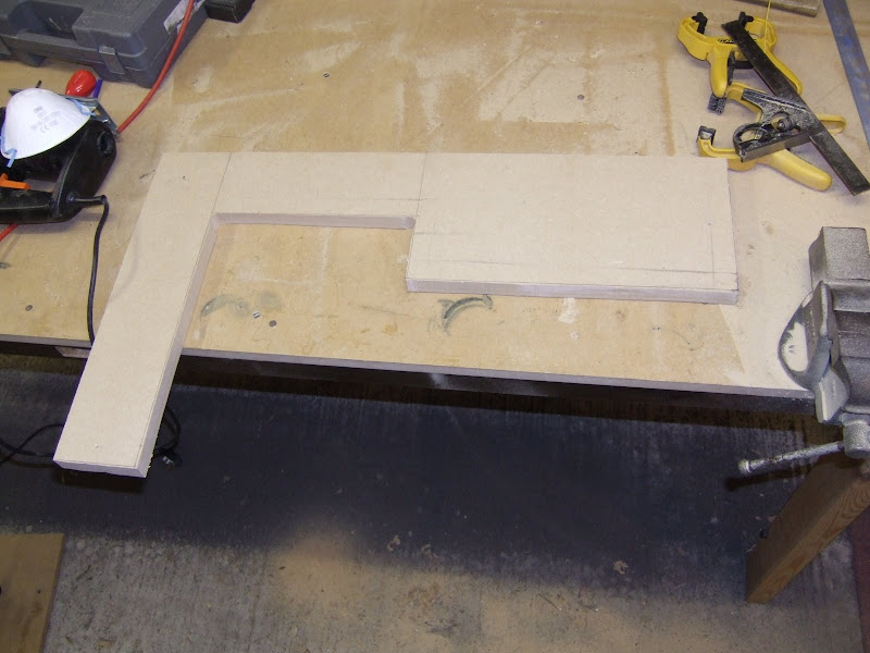
In order to get both sides precisely the same, I cut a sheet of 12 mm MDF diagonally and then nailed the two halves together. This allowed the original accurate edges to form the corner between the back and the base on both pieces.


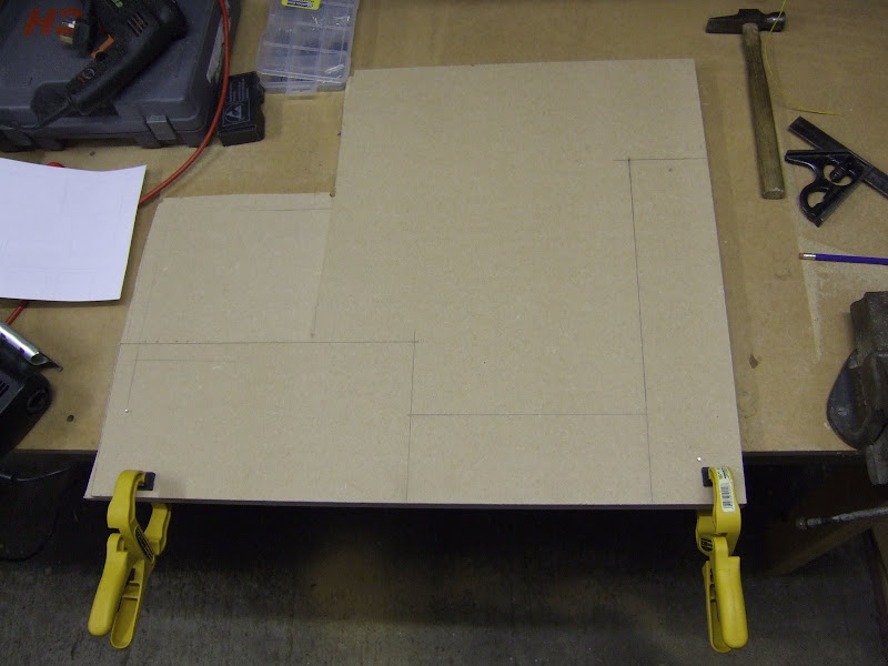
I then drilled large holes in the inner corners and cut the shape out with the bandsaw and a jigsaw. I tidied up the cut edges with a bench sander.


I made the joints with 12 mm beading, PVA glue, screws and nails.


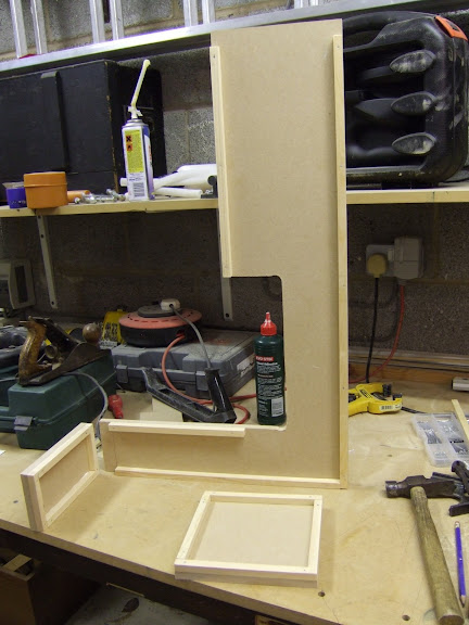
Here is the finished article.


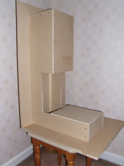
And here it is with the axes fitted and a large set square for scale. I used this to check the orthogonality and it was spot on.


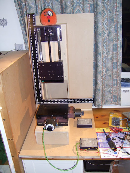
Unfortunately as soon as I had finished it I realised I had made a really basic mistake. All the right angles were braced by at least one sheet of MDF in its strong direction so I thought it would be pretty solid. However if I pushed hard against the side of the z-axis I could move it about 1 mm. Although this would be stiff enough for extruding plastic it would be no good for milling. What I had failed to take into account was that there is nothing to brace it against twisting around the vertical axis. Adding sides and a top to complete the outer box would have helped. Another idea I had was to fill it with concrete. When I thought about it a bit longer I realised this is why CNC mills are usually based on a gantry design. Reluctantly, I decided to scrap an entire weekend's work and start again without ever powering it up.

Monday 2 April 2007

Starting off on the wrong foot

My machine should probably be made from metal to give it enough stiffness for milling. However, I decided to prototype it in MDF first because it is much quicker and cheaper to work in wood. As it turned out it was just as well I did!

MDF is my favourite wood because it comes perfectly flat, with straight edges and right angle corners. No grain or knots to worry about either, the only problem is the dust which gets everywhere and is allegedly carcinogenic.

I have a foldaway workbench in the garage made from an old front door with a sheet of MDF over it. The door's original hinges are used to let it swing up from the wall and it has hinged legs that drop down as I pull it out. This allows us to keep a car in the garage, something very few households seem to do these days.


The bench has woodwork and metalwork vices and three interchangeable stations where I can mount my bench sander, drill press and band saw. These are stored on a shelf above the height of the car.


Unfortunately when I first put the shelf up I used the wrong sort of plugs for hollow breeze blocks. One day my wife and I heard a crash which sounded like a car crash in the front garden. We ran to the window but nothing was happening outside. We had just got a new TV with surround sound so we thought it must have been part of the film we were watching. The next morning when my wife went into the garage she found the shelf and all my tools on top of her car! It did so much damage she still hasn't forgiven me ten years on.

The first thing I did to start my build was to cut a base board 500 mm square from a sheet of 18 mm MDF. I placed this on the bench while I adjusted the band saw for the next cut. Somehow I managed to knock the sheet off and it landed on my big toe. The pain was the worst I have ever experienced. It left a pair of 18 mm tram lines across my leather shoe as you can just make out below :-


This is what it did to my toe :-


That put an end to that evening's work and left me limping for a couple of days. The toe recovered but the shoe didn't. I can see now why my dad always wore steel toe capped "totector" boots when he was working.

Sunday 1 April 2007

Its a plan

Having obtained some accurate and strong axes at a reasonable price a plan was starting to form. I decided to make a small but highly accurate milling machine. With this, and the small watchmaker's lathe I inherited from my dad,

I should be able to make a plastic filament extruder. I intend to mount this on the z-axis to make an FDM machine capable of making the plastic parts of the RepRap Darwin. I should also be able to mill and drill the Darwin PCBs. Once I make the Darwin I will be synchronised with the RepRap project and thus able to make the successive generations, whatever they may be, because the RepRap idea is that each new generation can be made by the previous one.

That was my original aim but my axes should out perform the Darwin axes in all respects except build volume. Darwin aims to achieve 0.1 mm accuracy with a 300 mm cube build area. I expect to get 0.006 mm accuracy on X and Y and 0.05 mm accuracy on Z over a 150 mm cube. That means rather than just using my machine as a RepStrap I will continue to use it for anything that doesn't need the larger build area. I then got the idea that I would be using many different heads on the same Cartesian engine, hence the name HydraRaptor. Initially these will be manually exchanged but I have a plan to mount the heads, spoke like, on a rotating wheel fastened to the z-axis.