Saturday, 26 May 2007

Tooled up

I wired up and tested the tool height sensor that I made last week and it worked fine. It gave consistent and repeatable results. Rather than use an OR gate I just connected two of the pins to two inputs of my micro and did the OR in software. I configured the micro to have internal pull downs and I connected the third pin of the sensor to 3.3V via a current limiting resistor. This configuration allows for the tool to be connected to ground, in which case either the tool touching the disk or any of the three contacts being broken will take at least one of the inputs low.

The software just plunges the tool into the sensor at full speed. As soon as one of the inputs goes low it backs up 1 mm and then descends slowly until it breaks the connection again.

There was only one small problem ... I made it for the wrong corner of my XY table! Having it on the right meant that the vacuum pipe had to clear it so could not be as close to the workpiece as it could otherwise be. No problem, I just got HydraRaptor to make another base for the left hand corner. I designed the part in Visio and then manually made a Python script to mill it. At some point I need to find a free CAD / CAM program for things like this.

Here is the drawing :-


This is what the script looks like :-
from Hydra import *
from Arc import *
from Tool import *
from Line import *

hydra = Hydra("10.0.0.42")
top = 6.1
base = -0.3
hydra.work_origin = (-50,0)
hydra.work_height = top
hydra.measure_tool(end_mill)
hydra.tool = end_mill

tr = end_mill.radius

# recess
hydra.drill((0,0), 18.0, top, 5.6)
hydra.drill((0,0), 15.0, top, 5.6)

# spring well
hydra.drill((0,0), 10.0, top, 3.0)
hydra.drill((0,0), 2 * tr, top, 3.0)
hydra.drill((0,0), 7.0, 3.0, 1.0)
hydra.drill((0,0), 2 * tr, 3.0, 1.0)

# screw hole
hydra.drill((13.5,19), 5.0, top, base)

# outline
outline = [Line(-10,32.5), Arc(-9,32.5,-9,33.5,-1), Line(26,33.5), Arc(26,32.5,27,32.5,-1),
Line(27,-9), Arc(26,-9,26,-10,-1), Line(0,-10), Arc(0,0,-10,0,-1)]

hydra.mill(outline, top , base)

del hydra
And here it is installed :-


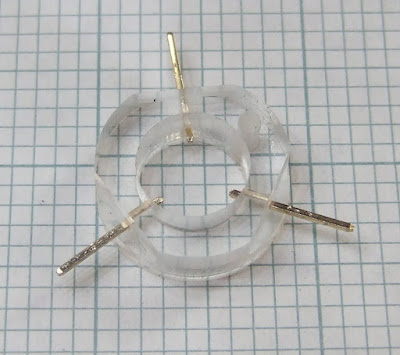
You can see that I used JB Weld to glue the pins in. I did that to stop them moving when I soldered the wires on, as Perspex melts very easily.

Below is a video of the new base being made. You can see the right handed version of the tool sensor being used at the beginning. I upped the feed rate to 15mm per second with no problems. Even so it took more that 15 minutes to make the piece so I have speeded up the video by a factor of two.


Obviously it is important to switch the spindle motor off when measuring the tool! At the moment I am doing this manually. I forgot once but I got away with it because it measures so quickly. The next job is to put the motor under software control.

Sunday, 20 May 2007

Let there be light

Taking close up video footage requires quite a lot of light because the maximum exposure is limited by the frame rate and zooming in wastes a lot of the light hitting the lens. I have previously been using a random collection of incandescent spot lights totalling about 200w. These gave an overly warm white balance with my camera, a Fuji Finepix 900, plus they tended to get in the way and gave off a lot of heat. I decided to try LED lighting as that seems to be the future. I suspended twelve 1W white LEDs over the top of the machine on a sheet of aluminium laminate plus another six on a strip of copper PCB laminate under the box that supports the Z-axis.


The LEDs were wired in groups of six in series and connected to the 24V supply with a small series resistor. I adjusted these to get about 300ma. A constant current source would have been better but I didn't have any suitable medium power transistors to hand and the supply is well regulated.

Here is what they look like in the machine viewed from below, they are not visible with the normal camera angle from above.


They seem to be bright enough for shooting video and they are only using 18W, 10 times less than my spot lights. If you compare my second video with the first you can see the difference although I didn't have the bottom six installed at that point.

Friday, 18 May 2007

How long is your tool?

I decided to make a tool height sensor as a high priority because finding the Z = 0 setting manually is time consuming and risks breaking expensive milling / drill bits. I got my design inspiration from The "One Penny" Touch Probe. I basically turned it upside down. My plan was to have a spring loaded disk pressing upwards against three contacts. Any movement of the disk downwards must break at least one connection. Note that the circuit in the aforementioned article is a little bit more complicated than it needs to be. Rather than use a three input OR gate you can just connect one of the contacts to ground and use a two input OR gate. That also dispenses with a connection to the disk.

Things went well to start with. I milled a ring with three flats on it out of 6mm Perspex. I drilled into the flats and inserted three gold plated pins extracted from a 0.1" header.


I then milled a base which bolts into one corner of the tray on top of my XY table. It has a circular recess to locate the base of the contact ring and a blind hole to house the spring. The corners are all radiused.


The small screw hole in both pieces was drilled manually with a small drill press, the rest was all done by Python script driving HydraRaptor with a 1/8 inch end mill. Here is a video of the ring being made, the flats were added by a third pass :-


The perspex milling went remarkably well at 10 mm per second feed rate, 0.1mm cut. I glued the sheet down onto the sacrificial base (floor laminate) using plasti-kote stencil mount. This worked well but I had to leave it 24 hours to dry because it was pretty much sealed between the two sheets. I removed it from the workpiece afterwards with Stain Slayer tar and grease remover.

The only slight defect was that the parts are slightly undersized for most of their height, but a bit bigger at the bottom. At first I thought that the tool wasn't plunging deep enough into the base material. I tried increasing that with no effect, so the explanation I came up with is that the tool gets a bit clogged with perspex and that rubs against the work piece making it slightly undersized and gives it a polished appearance higher up the edge.

Flushed with success, I thought making a conductive disk would be a doddle but it turned out much harder than I thought. My first idea was to mill a 9.5 mm disk out of PCB material. I stuck that down with stencil mount but I only left it to dry a few hours. It came lose while milling, creating an egg shape.

My second idea was to turn down a cupro-nickel disk on my watchmaker's lathe. I can't say where this disk came from but I can say that it cost exactly 5p. My plan was to hold it by its outside edge in a chuck and plunge a tool into the face to get the correct diameter. After an evening of trying every tool I had and shaking the lathe apart I realised that is not an operation you can do on a lathe. Normally you cut across a face or along the length of the piece. In that case only the leading edge of the tool is actually removing metal. If you try to plunge a tool into the face of the workpiece the whole of the tool width is trying to cut. It just digs in and stalls the lathe. Perhaps a very thin tool might work but I don't have one. The only way to reduce the diameter with the lathe is to turn it from the outside but then there is nothing to hold it by.

My third idea was to turn down a bit of 10mm brass bar and then cut the end off to make a thin disk. This worked at the second attempt, after I had improved my lathe skills a bit. Here are the three rejects :-


And here is the one that worked :-


I made a 5mm stalk on the back to locate the spring :-


And here is the assembled sensor :-


To my amazement when I metered it out there was no connection between the contacts. How could brass pressed against gold not make contact? After close inspection I realised that the disk was resting on small Perspex burrs where I had drilled the holes for the pins. I removed the pins and scraped off the burr with a pen knife and that fixed it.

Tomorrow I will wire it up and see how it performs. The only thing that worries me is that the brass might tarnish with time. At least it will fail safe if it does. I have a small gold watch case that I can cut a disk from if need be.