Not much to report as I have had little time to spend on HydraRaptor this week, should get more done this weekend though.
On the firmware front I got as far as writing the Ethernet PHY driver. This is the part of the Ethernet controller concerned with actually sending the signals down the wire. Back in the days of 10MB Ethernet this was a relatively simple line driver. With 100MB it is a lot more complicated and generally involves a DSP to compensate for signal distortion in the cable. Quite often these are separate chips but the MC9S12NE64 has one built in.
Despite the internal complexity, the interface to a PHY is straightforward. The driver just has to configure it and then wait for it to report that the link is up. One slight wrinkle I came across is that there is a bug in the silicon that drives the activity LED. Apparently the pulse it generates is too short to be seen. You can either stretch it in hardware or disable the hardware control of the LEDs and do it yourself in software, using the pins as general purpose I/O.
The next thing to do is write the MAC driver. This part of the chip is responsible for sending and receiving Ethernet packets.
Saturday, 21 April 2007
Saturday, 14 April 2007
Stacking up
You may notice my blog entries slow down a bit as I have now finished catching up so it has become real time. Hopefully I should get less complaints about mixing tenses in a paragraph!
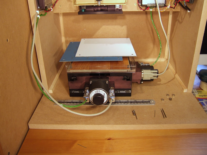
I have made a clamping system to fasten PCB material to my XY table. The test using masking tape worked surprisingly well but I need to be able to turn the board over whilst maintaining alignment for double sided PCBs.

The bottom layer you can see in the picture is a plastic tray to catch the dust from milling. It is the bottom half of a Ferrero Roche chocolate box. They make great boxes but unfortunately my wife does not rate the chocolates much.
The next layer is a sacrificial piece of laminate flooring to support the PCB and prevent breakout when it is being drilled. It seems a shame to cut it up and use it this way but at £6 per square meter this piece only cost £0.17 and I can use both sides at least once.
The blue sheet is single sided PCB material. I will use the machine to route a square aperture in the middle of this at the limits of the XY table's travel. The PCB being made will rest against one corner of the aperture to locate it. Being double sided it will stand proud by 0.3mm due to the extra layer of copper.
The top layer is a 3 mm aluminium and plastic laminate that I will use to clamp the board down on two edges. I will use the machine to route a slightly smaller aperture in it than the layer below so that it overlaps slightly. The other two edges of the board will be held down with masking tape.
The whole lot is clamped by four 2 BA nuts on threaded rods that fit holes in the XY table. My XY table is imperial and the rest of the machine metric!
I am currently working on the firmware. I have replaced the test code I cobbled together just to try things out with an interrupt driven 3D Bresenham line drawing routine. Although I probably will never need to step Z at the same time as X and Y it was easier to code the general case. It makes some interesting sounds when in runs because the motors play a three note chord depending on the gradient of the line.
The code is written in C in an object oriented style even though C is not an OO langauge. I always tend to code like that and have done so since before I knew what OO was. The three axes are represented by structs that store the position, etc, along with function pointers for stepping and reading limits which is axis dependent. That way I can reuse the same Bresenham and homing code for all three axis.
I have made a clamping system to fasten PCB material to my XY table. The test using masking tape worked surprisingly well but I need to be able to turn the board over whilst maintaining alignment for double sided PCBs.
The bottom layer you can see in the picture is a plastic tray to catch the dust from milling. It is the bottom half of a Ferrero Roche chocolate box. They make great boxes but unfortunately my wife does not rate the chocolates much.
The next layer is a sacrificial piece of laminate flooring to support the PCB and prevent breakout when it is being drilled. It seems a shame to cut it up and use it this way but at £6 per square meter this piece only cost £0.17 and I can use both sides at least once.
The blue sheet is single sided PCB material. I will use the machine to route a square aperture in the middle of this at the limits of the XY table's travel. The PCB being made will rest against one corner of the aperture to locate it. Being double sided it will stand proud by 0.3mm due to the extra layer of copper.
The top layer is a 3 mm aluminium and plastic laminate that I will use to clamp the board down on two edges. I will use the machine to route a slightly smaller aperture in it than the layer below so that it overlaps slightly. The other two edges of the board will be held down with masking tape.
The whole lot is clamped by four 2 BA nuts on threaded rods that fit holes in the XY table. My XY table is imperial and the rest of the machine metric!
I am currently working on the firmware. I have replaced the test code I cobbled together just to try things out with an interrupt driven 3D Bresenham line drawing routine. Although I probably will never need to step Z at the same time as X and Y it was easier to code the general case. It makes some interesting sounds when in runs because the motors play a three note chord depending on the gradient of the line.
The code is written in C in an object oriented style even though C is not an OO langauge. I always tend to code like that and have done so since before I knew what OO was. The three axes are represented by structs that store the position, etc, along with function pointers for stepping and reading limits which is axis dependent. That way I can reuse the same Bresenham and homing code for all three axis.
typedef struct axis {
    sword   pos;                        // Current position
    sword   min;                        // Limits
    sword   max;
    sword   steps;                      // Number of steps to do this line
    sword   dir;                        // Direction of each step +/-1
    sword   acc;                        // Brezenham accumulator
    void    (*set_dir)(bool);           // Virtual function to set direction output (X,Y only)
    void    (*start_step)(void);        // Leading edge of step pulse
    void    (*end_step)(void);          // Trailing edge of step pulse
    bool    (*mlimit)(void);            // Read the negative limit
} axis_ty;
Wednesday, 11 April 2007
The powers that be
When trying to make parts of my machine stiffer I got to wondering about the relationship between a material's thickness and its resistance to bending. It is obviously not a linear relationship because as a sheet gets thicker not only is there more material to resist bending, but the outer layers have more leverage than the inner, so it must be at least a square law. I tried googling this for some time but failed to find a formula. I did find a comment on CNCzone by somebody that thought he recollected it being a fourth power law. I can believe this because we recently had two versions of a metal box made at work, one in 0.5 mm steel and the other 0.8 mm. While the thin one was quite flimsy the 60% thicker one was very solid. Any mechanical engineers out there?
I came across another fourth power law recently on the website of the company that made my XY table. If you have a servo system moving something from A to B as fast as it can go, then going twice as fast requires 16 times the power. Some video lectures, and a lot of other useful info about servo systems, are here www.neat.com/products/corner/default.asp.
The highest power law I have ever come across is that incandescent bulb lifetime is inversely proportional to the 12th power of voltage, see www.allegromicro.com/en/Products/Design/an/an295012.pdf. Can anybody beat that?
Subscribe to:
Comments (Atom)

