Loading [MathJax]/extensions/tex2jax.js

Thursday, 28 January 2016

A bridge too far

This version of the Mendel90 fan duct that accommodates the E3D V6 hot end happens to be a shape that is surprisingly difficult for slicers. It is because of the shallow sloping slanted bridge.


Skeinforge

I slice everything I print with Skeinforge, so the normal Mendel90 parts are designed around its limitations. It normally does a good job of detecting bridges and aligning the infill to span the gap. Its big limitation is that it does the infill for an entire layer in one direction, whereas it should at least be per island. However, even with the original flat fan duct it doesn't see the first layer of the roof as a bridge.


Left to its own devices it does this for the bridging layer.

Layer before roof: -


First bridging layer: -


Clearly this doesn't print well because the ends of the infill don't land on anything. The orange section of infill has nothing under the yellow internal edge, so the loops just fall down.

Filament runs can't start, end or change direction when there is nothing under them, whether it be infill or outline. I don't know what algorithms slicers use but if I was writing one I would generate the infill for an island at the default angle and then check that all the end points land on something below. If not then I would try aligning it with each of the straight sides of the outline, starting with the longest first, noting how many endpoints miss. In most cases that would yield a direction with no misses. In the unlikely event it didn't then I would go for the direction with least misses and try reducing them by tweaking the angle. If there is no solution then I would issue a warning and miss out the lines that can't be printed.

To get around Skeinforge not spotting the bridge I set the infill starting angle to 90° so that the first bridge layer happens to be in the right direction anyway.


This workaround is OK when you have just one layer that bridges. With multiple layers you might need to slice with different angles and then splice the gcode together, but that is getting very inconvenient.

I normally print Mendel90 parts with 0.4mm layers, but I print the duct with 0.35mm layers in order to stretch the filament tighter, so that it bridges the large gap with less droop. The fact that it isn't detected as a bridge means that special bridging settings can't be applied.

When it comes to the new duct this strategy doesn't work because every layer of the sloping bridge advances left with nothing underneath. So consecutive layers are all bridges at the left edge. With normal 90° infill rotation every second layer has its infill changing direction in mid air. It is supported a little way back, so only small loops hang down, but that makes the inside of the duct very ugly and can't be good for airflow. Also if I print it with 0.35mm layers then the extra tension makes it tend to curl upwards and brush the nozzle, leaving brown marks on the top surface.

I could set the infill rotation to zero so that every layer is the right direction for the bridge but that would lead to a weak object, especially where the infill is sparse, so I haven't tried it. What is needed is a slicer that can split the sloping roof layers into a left unsupported edge that is printed as a bridge and the rest that is printed with normal diagonal infill. I know that other slicers can have different infill patterns within one island, so I decided to try them out with this object.

Cura 15.04.3

Cura seems to display infill as solid yellow in its layers view, so I used gcode.ws to display the gcode.

Cura doesn't detect a bridge and just uses diagonal infill all the way. Interestingly it doesn't connect the ends of the infill, it does a short move at high speed with no retraction. Also it doesn't seem to have any retraction when it moves significant distances across the infill. This is one of the reasons I don't use Cura. I need retractions before all moves longer than say 1mm otherwise it leaves a trail behind and the next line doesn't start properly as there is missing plastic.

KISSlicer 1.1.0.14

KISSlicer shows some errors in the STL but the colour it uses to highlight them isn't in the key, so I don't know what it thinks is wrong. There are no errors in Netfabb Basic so I am pretty sure the file is OK.


It too doesn't recognise the bridge and just does normal diagonal infill over it, using a colour scheme that is very difficult to see!


One odd thing is seems to do is inset the internal walls a little further on the last layer below this one, perhaps to give the infill more area to land on.

Slic3r 1.2.9

Slic3r actually detects it as a bridge but gets the angle slightly wrong.

Two infill lines start or end in mid air. I discovered though that if I rotate it 90° the infill comes out correct.

This is a shame because I orientate it length ways for printing. That is because on a moving bed Y axis you want to minimise the Y movement to keep the object in warm air.

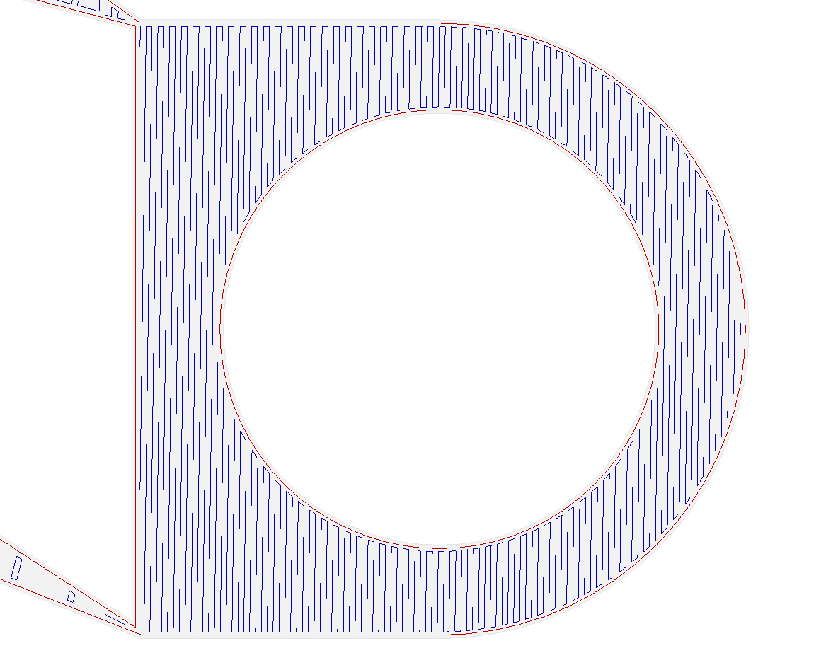
The next layer does exactly what I want. I.e. it does horizontal infill where there is nothing underneath but reverts to normal diagonal infill where there is something below.

So far so good but after a few more similar layers it starts to go a bit wrong.

It gets the boundaries of the bridge region wrong. It has a few lines of infill turning in mid air at the right hand side. Further up the slope it gets the left hand side wrong as well. I suspect it is because the slope slants left to right.

Further up it gets a bit more strange.

I haven't tried printing it but I suspect it would come out not too badly, with just a few small loops hanging down. At least it does logically the right thing, shame about the bugs in getting the bridge angle and region accurate.

CraftWare 1.13 beta

This is a late addition suggested in the comments. Perhaps the nicest user interface of all but it doesn't detect bridges at all in this object.


Simplify3D 3.0.2

Since none of the free slicers I know of got this right I decided to try a paid for one. With a single outline it fails to detect the first bridge and just does diagonal infill in mid air.


On subsequent layers it does seem to divide the layer correctly into a bridge region and a normal region but gets the infill direction in the bridge area completely wrong.


With two outlines it gets the main bridge correct but the slope now doesn't have a separate bridge region, just diagonal infill. That is except for just one layer and that also has the direction wrong.


 The odd layer corresponds with the solid support diaphragms over the screw holes.


This does print slightly better than the Skeinforge one but only because the extra outline means the infill lines don't need to overhang quite as far.

Conclusion

So in summary I can't find a slicer that gets this correct but Slic3r is the closest. Of course they all offer support material but that would be difficult to remove inside the duct and there in lies another raft of bugs, if you pardon the pun. See below: -


Wednesday, 27 January 2016

Telequipment D32 trace rotation fix

Another ancient piece of equipment I have is this Telequipment D32 mains / battery operated portable oscilloscope.


Telequipment is an old brand name used by Tektronix in Europe. I think it was made in about 1972 for servicing TVs. I bought it in a broken state from a friend of a friend in the mid 1980s. The six NiCad D cells had gone short circuit and the mains transformer was burnt out. I replaced both of those and as far as I can remember that was all I had to do to get it working.

I did get a lot of use from it as for many years it was the only working scope I had. I haven't used it much in recent years though because I now have several much better scopes. It is the only battery powered one I have, although I do have two USB digital scopes which are battery powered if I run them from a laptop.

I powered it up fully expecting the NiCads to have died again, but amazingly they still work to some extent. The only thing wrong with it was the trace was slanted and the trace rotation control didn't have enough range to correct it fully. It seemed to max out in one direction and then have a large dead band.

I did a bit of research and managed to find the schematic. I must admit that somehow the fact that a beam rotation circuit is needed because of the earth's magnetic field had completely passed me by, or else I once knew and have since forgotten. This is despite building my own scope with valves (vacuum tubes) when I was 13 and using CRT scopes for many years after.

The rotation circuit is below. After looking at it and making some measurements I was surprised to find it to be a design fault rather than a faulty component.


The base of TR301 can be varied between ±7.5V with R303, so one would expect the emitter follower to drive the coil over that range with a VBE offset. The problem is the coil has a resistance of about 1kΩ, so the pull down resistor R314 can't drag it below -3.5V. This means the control has no effect for a significant part of its travel and the range of the correction is asymmetrical.

To fix the problem I removed R314 and replaced it with a PNP emitter follower. That gives push-pull symmetrical drive between about -6.8V and 6.8V. The only dead band is a small one around 0 due to the VBE drops (classic crossover distortion). It also has the advantage of not wasting the current through R314, all the current now flows through the coil.

This is a view of the board before the mod. It is ancient technology, all discrete transistors and hand routed PCBs, including vias made with what looks like soldered in brass rivets.


I don't know why all the transistors are socketed. The only other time I have seen that was in a Russian transistor radio, but they were germanium PNP transistors, so may have been unreliable. These are silicon planar epitaxial so should be reliable and never need replacing. Perhaps they did it because they thought soldering would damage them. Or perhaps they were just old school designers used to valves.

Anyway the scope is a joy to work on because all the PCBs hinge out to allow access to both sides with the scope still operational. See www.youtube.com/watch?v=BOeEbyIllcM for a look inside a D32.

Here is a view of my modification: -

I replaced R314 with a 2N4403 (any PNP transistor should work) and linked the base to a handy via. Don't worry about the proximity to the ceramic capacitor's lead, it is the same net.

So a simple mod but I don't understand why I need it now. Perhaps the earth's magnetic field has changed since I last used it. It was about a decade ago!

Update

The scope has always had a delay between switching on and starting up. The power LED comes on about a second after it is switched on.  This got longer and longer and then it stopped starting reliably at all. I had always assumed the delay was caused by a capacitor charging in a bias circuit for the inverter but on examination of the schematic I fount that wasn't possible because all the capacitors have a low impedance supply.

It turned out the be the on off switch. I measured about 3V across it in the on state. The contact resistance measured 0.3Ω but that should only drop 0.3V at 1A, so it seems to be a strange non-linear resistance and it must get lower over time as it heats up.

The switch is part of the brightness potentiometer and it is operated by pulling the knob out and pushing it in. Normally potentiometers with switches operate it at the start of the rotation but this allows the brightness setting to be retained. It is also a small form factor so I didn't think I would be able to find a replacement. As it is riveted together I didn't think I would be able to repair it or even get any switch cleaner into it.

It is actually a two pole switch, the second pole is used to change the charge current of the battery to include the scope current when on. I figured 0.3Ω would not affect that circuit as it has 150Ω in series, so I swapped the connections over. It now starts instantly although it does take time for the tube to warm up of course.