I have been asked for dimensioned drawings of the extruder. I made these by manually inspecting the 3D models in ArtOfIllusion. It is not the easiest application for extracting dimensions so I made 2D drawings in Visio which does have good dimensioning tools. I then made Python scrips to do the milling. My dimensions may differ in places but I did make the extruder from these drawings and it does work. I tightened up some of the hole clearances because my milling machine holds much tighter tolerance than FDM.
This is the motor shaft coupler. I adjusted the slot to suit my GM3 motor. I think there are now two versions of this part. The official design is tapered but this is not necessary with the offset motor mount so I simplified it to a cylinder.
Here is the finished article milled with a 2.22 mm bit. The step on the outside and in the shaft slot are there because my milling tool's shaft is wider than the bit, so to go deeper than 9mm I need to have some clearance. The material is some sort of metal loaded resin.
Here is the clamp drawing I used. It has now been superseded by a larger design. Note that I adjusted the hole for the PTFE to suit my 12mm rod. I think the official design was 10mm but is now 16mm. I also widened the slot to allow the 2.2mm milling tool to get in and added some extra mounting holes to suit my machine.
I milled it from 9mm Delrin.
Here is the pump drawing :-
The poly channel on the official version slopes outwards at the entry but that is only needed for the version without the offset motor.
And here is the milled version :-
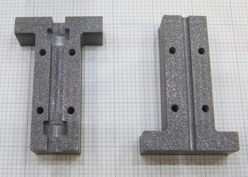
The material I used is not as slippery as CAPA so, to reduce friction in the channel, I smoothed it with emery paper, polished it with metal polish and sprayed it with PTFE dry film spray.
I split the motor mount into three pieces for milling from a sheet of 5mm perspex. I fixed the pieces together with M2.5 screws, tapped into the perspex.
If anybody wants the Visio source file it is here:- forums.reprap.org
Saturday, 27 October 2007
Tuesday, 23 October 2007
They don't like it up 'em!
How is this for bad luck :-
I was trying to connect a scope probe to the far side of a two row connector on my machine. I made a small hook from a piece of wire with a bit of insulation to get it past the front row.
I inserted this with the power turned off. Unfortunatly, and almost unbelievably, the far end of the wire manage to find its way into a hole leading to the mains live terminal on my solid state relay. That was the only thing on the live side of the mains switch.
Massive bang! Blew the crap out of HydraRaptor and my ADSL router. My PC is crippled is well, it no longer runs at the correct front side bus speed and insists I haven't got an 80 pin IDE cable.
This is the CPU of my axis controller :-
And this the micro from my extruder controller :-
I expect all the rest of the electronics is fried as well, so pretty much the end of HydraRaptor. The only lucky thing was that I was holding the insulation, otherwise it might have been the end of me as well!
Stretching a point
In his article: x-idler-bracket-continued Vik Olliver alluded to the fact that you can extrude filament with a smaller diameter than the hole in the nozzle. I did some experiments to see how fine I could go. In fact the final filament diameter is simply determined by the feed rate of the extruder and the travel rate of the nozzle, or in my case the bed. The filament stretches to the length that matches the rate of travel while it is still liquid. You can then calculate the mean diameter from the volume of material extruded. The nozzle height has to be a bit less than that mean diameter and then the width becomes a bit wider.
Here are three 20 x 20 x 20 open cubes with different wall thicknesses :-
The first was 1mm diameter filament extruded at 4mm per second with a height of 0.8mm giving a wall thickness of about 1.2mm.
The second was the same feed rate but with the extruder traveling over the bed at 16mm per second to give 0.5mm filament, the same as the nozzle hole diameter. The height was set to 0.4mm giving a wall thickness of about 0.6mm. As you can see it warps more but I expect it would behave if it was building a solid object. The bottom layer which was stuck to the table has better corner definition.
The third attempt was 0.35mm filament extruded at 16mm per second with a hight of 0.28mm and a width of about 0.5mm. As you can see holes started appearing but I think that was just because the sides buckled so badly. Interestingly the holes can be bridged by filament above that needs no support. Again, I think this would be OK making solid objects, or at least objects with thicker walls.
This is really good news as it means I can get down to the sort of resolution commercial machines get (0.25mm) without having to have a very small nozzle aperture, which would limit the flow rate. It remains to be seen what effect stretching has on the polymer but as it is still liquid at that point I think it wont increase the contraction much, if at all. It does mean I need very fast head movement to keep up the deposition rate, about 64mm per second. I think my machine will do that if I reconfigure the steppers for speed rather than torque, a simple one wire change.
Subscribe to:
Posts (Atom)