Showing posts with label HDPE. Show all posts

Tuesday 16 October 2007

Scaling new heights

In my article laying-it-on-the-line I showed how I arrived at this test shape, a 20mm open ended cube :-


I decided to try different sized shapes to see how the process scales. It turns out that it doesn't and 20mm cubed is the magic size that is easiest to make!

The first thing I tried was taller :-


As you can see at 50mm tall it is starting to sag and 100mm is hopeless. The problem is that as the height increases, the plastic already laid down contracts as it cools and leaves the nozzle high and dry. I fixed that be reducing the Z increment from 1mm per layer to 0.95mm. That allowed me to make a good 20 x 20 x 95mm square tube :-


I presume with this increment I can keep going up, but who knows, I thought that at 20mm!

Next I tried low and wide. This was an attempt to make 120 x 120 x 20mm :-


I stopped it when the first two layers failed to weld. This was because with an object this large, by the time it has traced the perimeter to start the next layer, the first layer has cooled down to room temperature. In my post sticking point I predicted that to make an instantaneous weld between molten plastic and plastic at room temperature requires the molten plastic to be at temperature

T = 2 x Tm - Tr, for HDPE and 20°C this means about 240 - 250°C.

I set my extruder to 240°C and made this mess :-


I don't like running the extruder that hot because, although HDPE is not supposed to burn until 350°C, it smells like burning plastic and the end of the nozzle is glazed black. Also, the toothbrush that wipes the nozzle is showing signs of melting.

The object came unstuck from the foam board because of the extreme corner curling due to shrinkage. This is a fundamental problem with HDPE and room temperature FDM. HDPE shrinks about 2% when it cools from its melting point to room temperature. Commercial FDM machines use ABS, which has a lower shrinkage, and they keep the work piece in an oven close to the melting point. That means the hot plastic does not need to be so much hotter than the melting point, and most of the shrinkage occurs after the object is complete. The problem here is that the first layer cools and shrinks before the next layer lands of top. The next layer is bigger when it welds on top but then it shrinks, contracting the bottom layer more. Each subsequent layer increases the tension on the layers below. The bigger the object is, the worse the effect is because the mismatch between the size of the hot layer and the cold layer below it is bigger in absolute terms.

Following in Forrest's footsteps I tried laying down a raft of HDPE first to anchor the object to the foam base. The raft is 120 x 120mm but the object is now only 100 x 100 x 20mm.


As you can see that gives a big improvement but it wasn't strong enough to hold the corners down fully. A bigger raft, and perhaps a second layer might help but as it was an hour to build the raft and half an hour to build the object I didn't bother trying again. The blob, by the way, is where the firmware crashed on the last layer!

Here are some 40 x 40 x 20mm tests made with rafts, the second one had a bigger raft:-


Here the corner curl with a raft is comparable to the 20 x 20 x 20mm test without a raft showing how this effect gets dramatically worse as width increases.

Next I tried tall thin objects :-


Both were made on rafts and, the first is 15 x 15x x 75 mm, the second is 10 x 10 x 100mm. The photo is not very good but they both flare towards the bottom. The one on the left has an untidy surface as each layer is not well aligned with the layer below it and the one of the right has a completely wavy surface like basket work.

The reason for this is that because the perimeter is shorter, the layer below is still molten when the next layer is extruded on top of it. It moves around giving an untidy surface and also does not resist the contraction of the layer above. The bottom few layers are the correct size because they are welded to the solid raft but the layers above are too small as they have contracted inwards. A 5 x 5mm test shows this effect even more :-


The only way around this is either to wait for the layer below to cool, speed up its cooling with a fan, or extrude very slowly. I decided to experiment with a fan. It was immediately obvious that if you have a fan blowing near the nozzle you have to insulate it otherwise it doesn't reach its target temperature.

The RepRap design uses fiberglass wool but I wanted to be able to see the state of my heater so I decided to make a transparent cover. I started with a plastic test tube, donated by my wife, which used to contain bath salts.


I cut the end off this and drilled a hole to clear the nozzle. I converted a large plastic nut into a mounting flange by stripping out the thread on my lathe so that it was a push fit.


Here it is mounted on the extruder :-


The first fan I tried was a small North bridge cooling fan. It was so light that I could mount it on a stiff wire attached by ring tail crimps and bolts. :-


Unfortunately it wasn't very powerful so the next fan I tried was a PC case fan complete with speed control and blue flashing LEDs.


This worked a lot better but it is difficult to get it as close as I would like it. Here is the tallest thing I have made so far, it is 10 x 10 x 150mm. At this point I changed to 4mm per second travel and a feed rate to give a 1mm filament. I found that you can get finer filament just by stretching it as it leaves the nozzle so the work I did with flow rate and filament size is not really relevant. I had to reduce the layer height to 0.8mm.


This worked well on the windward side, with a nice tight corner, but not so well on the leeward side. The corner away from the fan is more rounded and the layers are less tidy. A cross section shows that the two sides cooled by the fan are straighter and longer.

The 5 x 5 x 20mm test is much improved but its surface area is so small that the fan fails to keep it cool enough. I think the only option with something as small as this is to slow down, and possibly drop the temperature.


Again the leeward side is not as good. The filament short cuts the corner because the layer below is not strong enough to hold it in place. I think to make the fan effective a cowling and duct is needed to get a strong flow of air directed downwards around all sides of the nozzle.


I have noticed that there is always an excess of material at the corners. This is because the head makes a perfect right angle but the filament has a minimum bend radius and takes a short cut. I am not sure how to compensate for this. I can't really pause the extruder because its response is too slow, so I either have to speed the head up as it takes a corner, or perhaps make it move in an arc that matches the bend radius rather than a right angle.

And finally here is an improved version of the magic 20mm cube :-


This is with the benefit of a raft, finer filament and fan cooling. The corners are a bit sharper and the corner curling a bit less. The reasons why this turned out to be the optimum shape are :-
  1. It is small enough that the filament does not cool too much when you go round it.
  2. It is large enough to make it long enough to traverse so that it does not stay too hot.
  3. It is short enough for the fan to be able to cool the back wall from the inside as well as the front.
  4. It is small enough for corner curling to not be too extreme.
From these experiments I now think I have a good understanding of how the parameters: temperature, flow rate, traversal rate, z increment and fan use affect the result. I have only looked at thin walled boxes, I expect solid objects to add more thermal and contraction issues.

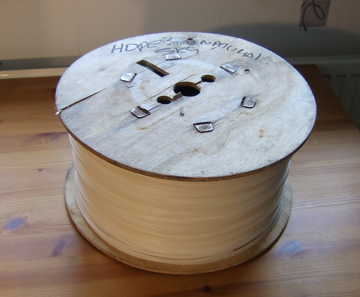
The only reason I am using HDPE is that it seems to be the only thermoplastic filament I can buy off the shelf in the UK without getting it specially made.

With a bit of trial and error I expect I could make the machine produce a wide range of shapes and some useful objects but therein lies the problem. It is not supposed to be trial and error. The dream is to be able to input an arbitrary 3D model, of any size within the build volume, and have the item appear a few hours later. At the moment I can't see how that can happen with room temperature extrusion of HDPE. Its melting point is too high and its contraction too great. Managing the temperature of the object being built is very tricky as the features of the object vary from large to small.

Thursday 4 October 2007

Sticking point

Over the last few days I have been working on getting my machine to lay down straight lines of HDPE filament. It was a lot harder than I imagined. Initially I could not get it to stick to anything. I knew Forrest, who has been pioneering the use of HDPE with Tommelise, had successfully used foam board as a base to extrude onto, and the RepRap design uses a sheet of MDF for CAPA. I didn't have any foam board to hand so I tried MDF and several other things with no success at all. In desperation I then tried slowing down the extrusion to 0.75mm per second and that did the trick. I found I could then extrude onto lots of things so I tried as many as I could think of to see the pros and cons. Today I got my hands on a piece of 5mm foam board as well.

This was 3mm thick cardboard, it didn't stick very well at the ends.


Blotting paper sticks better but the heat makes it wrinkle and it leaves residue when peeled.


Funky foam, my wife's contribution, sticks too well, it gets welded in and can't be separated cleanly.


A thin sheet of HDPE cut from a milk bottle. As expected it welds and cannot be separated. It could be a useful technique though, you would have to cut round the extruded object but it would be left with a strong smooth base.


Felt adheres very well and can be peeled off again but you would end up with a slightly hairy object!


MDF adheres well and peels easily but it does leave some residue fibres on the filament.


Anti-static foam from semiconductor packaging. This insulated the filament so well that it stayed molten too long causing the ends to stretch away. It sticks well but leaves a residue and a rough surface.


Foam board works very well despite having a glossy finish. That allows the filament to be peeled off cleanly and gives it a nice smooth surface. With this quick test there was no sign of damage to the board either but Forrest has reported the foam inside can melt.


This seemed to work so well I tried upping the speed to 4mm / second and that worked fine as well.


So I should have taken Forrest's word for it and saved myself some time, but it got me thinking why does it work so well? For the filament to stick, it must remain molten long enough to bind with the surface. That means something with low specific heat capacity and low thermal conductivity should work better. Paper has a specific heat capacity that is about the same as HDPE but that is only 0.2mm thick and then you have foam which is a good insulator. I had been trying things with some surface texture for the HDPE to bind to so I was surprised when something glossy worked. I don't know what makes the foam board surface glossy, maybe it is a thin layer of of plastic that binds with the HDPE by melting itself. Or maybe there is some molecular bonding going on, out of my depth here!

The next thing to do is to tidy up the line endings by adding a delay at the start and reduce the dwell at the end. Then I should be able to draw accurate outlines and fill them in.

I have started to think ahead to the next layer and what the requirements are to make it stick to the layer below. My mental model, which may be wrong, of how the heat flow works is to translate temperature into voltage, heat flow into current, specific heat capacity as distributed capacitance and thermal conduction as electrical conductivity. The extruded filament is then an infinite number of small capacitors, charged to 200V, linked by resistors. That will meet a bigger infinity of capacitors linked by resistors charged to 20V (room temperature). When the filament meets the already extruded layer the two surfaces behave like two capacitors charged to different voltages being connected in parallel. What happens in electronics is that the total charge is preserved so V(C1+C2) = C1V1 + C2V2, i.e. V = (C1V1 + C2V2) / (C1+C2) . If the capacitors are equal then V = (V1 + V2) / 2.

That means, if my analogy holds, that when two surfaces meet the temperature at the infinitely thin junction instantaneously becomes the average temperature, weighted by their specific heat capacities. In our case these are equal because it is HDPE at 200°C meeting HDPE at 20°C. It is my belief the junction will be at 110°C to start with. Heat will flow to it from the neighboring material on the hot side and away from it on the cold side. Since its temperature is half way between the two then these flows will be equal. The junction will stay at 110°C and this band of 110°C will start to spread to the neighboring material on each side. However, to form a weld the junction must reach the melting point of HDPE which is 135°C. The only way for this to happen is for the nozzle to stay around long enough to continue to supply heat. That puts a limit on how fast filament can be laid down and still bond.

To be free of this limitation the average of the temperature of the filament and the temperature of the workpiece must be higher than the melting point. If that is the case then it will weld instantly and there is no limit on extrusion speed. For HDPE and room temperature that would mean extruding at 250°C. Anything below that requires additional heat to flow from the nozzle to form the weld and hence sets a limit on how fast it can move away.

Sunday 30 September 2007

Dribble and smoke

Not a very good day today. I started by trying to lay down a 50mm straight line of HDPE. I completely failed and ended up smoking my machine!

The first problem I decided to tackle was extruding just the right amount of filament. This should be easy because I can instruct my extruder controller to turn the pump an exact amount. Using the equations I described last time, I know what feed rate is required to give a particular diameter filament and what its exit speed will be. The problem is that when the extruder stops, the filament continues to extrude slowly for a while afterwards. This is because the molten plastic, being non Newtonian, is compressible.

To start with I was getting about 12mm of overrun. I have noticed that the flexible drive made from steel wire gets wound up and stores some energy. With no power applied to the motor it actually unwinds a bit driving the motor backwards. By default my software was preventing that because it monitors the shaft position and applies increasing power as the shaft moves backwards until equilibrium is reached.

The host can instruct the controller to turn off the motor completely and let the wire unwind. That reduces the overrun to about 4mm. The shaft encoder sees the motor go backwards so, when it's told to move again, it regains all the backlash as fast as it can before settling down to the desired speed. Therefore, there is no loss cumulative loss of accuracy in letting the wire unwind and wind up again.

I expect the amount of filament overrun could be reduced further, or even eliminated completely by running the pump backwards a bit at the end. Unfortunately I can't do that because this is what happens to the steel wire when it is turned the wrong way:-


Because of this I designed my electronics to only be able to go forwards. Apparently this effect is not observed on the RepRap at Bath university. They are using 3mm wire, whereas mine is only 2.5mm, so that might account for it. I may see if I can get better wire that won't unwind. If so I will have to upgrade my drive to an H-bridge to allow the motor to be reversed. There isn't any spare room on my Vero board so I will either have to make a new one or make some sort of 3D creation.

In the meantime I decided to bodge round the problem. As well as the 4mm overrun when the motor stops, it also extrudes about 15mm when the heater is allowed to cool down and is then warmed up again. This is usually accompanied by a sharp cracking sound which sounds like trapped air bursting through the HDPE. I am not sure of the exact mechanism, but air must get in when the plastic is cold and contracted and then get trapped while it is heating up again, forcing some molten plastic out. Perhaps I have discovered a new type of pump with no moving parts!

So, before I can start extruding I need to remove the excess filament hanging from the nozzle. I did this by attaching a scalpel blade to one corner of my XY-table and having the machine visit it to wipe its nose just before starting to extrude. It is just a lash up at the moment, it would be better if it was 20mm above the table and a razor blade might be better, but it seems to work OK.


Of course, once the overrun has occurred and been removed, there is a net deficit of material which manifests itself as a delay before extrusion starts when the motor is switched on again. That has to be made up by starting the extruder in advance of moving the table for the first line segment.

So the next step was to lay down the filament on the table in a straight line. The first problem was that I discovered a bug in my software that meant the table only moved at half the specified rate. So any previous references to milling feed rates in this blog need to be halved!

The bug was easily fixed of course but I could not get the filament to stick to my table. When it hits the table it curls upwards into a loop and sticks to the side of the hot nozzle. The table surface I used for milling is made of upside down laminate flooring. It is covered with a textured layer of what I assume is probably some sort of vinyl. No great surprise it didn't stick, the next thing I tried was paper, a post-it note to be precise. That did not work either so the next thing to try was MDF. I taped an 18mm block to the the table for a quick test and raised the z position by 18mm, but I forgot to program it to raise up to clear it after visiting the knife. The result was the nozzle collided with the block and that pushed the thermistor wires so they touched the heater wires.

The result was quite spectacular, the thermistor wires, being quite thin, lit up like a light bulb before burning out. The thermistor is toast and so is the micro. Three volt micros don't like 12V up 'em!

I should have insulated the wires but I didn't have any insulation handy that would stand the temperature. Also three 3A diodes in series across the thermistor would have saved the day but it's a bit late now.

Fortunately I have a couple more micros and a spare thermistor but the machine will be out of action for 24 hours while the JB-Weld cures.

It is very easy to get a tool crash with a 3D machine and it usually causes a lot of damage. When I was using it as a milling machine I got into the habit of getting it to mime what it was going to do by running the program with a Z offset higher than the workpiece. I should have done the same thing this time.

Friday 28 September 2007

Equations of Extrusion

When I first tested my extruder I found that the filament diameter varied with the flow rate and temperature. This was contrary to what others have experienced so I decided to investigate further. It turns out that this is known as die swell and is caused by non Newtonian fluids expanding after they have been squeezed through a hole. Apparently it is a very complicated subject.

To get an idea of what was going on I designed my extruder controller to be able to make measurements. Rather than drive the motor with open loop PWM I used a shaft encoder with proportional feedback. Instead of specifying what PWM setting to use, the host specifies how many shaft encoder steps to move and at what rate. The extruder controller then adjusts the PWM to maintain the correct shaft position at any given instant. Assuming the filament does not slip against the drive screw, that means I can extrude a known volume of plastic in a known time to the tolerance of the the original feed material. The host can then ask the controller what the total on time and off times have been so that it can calculate the average power that has been used.

My temperature control works in a similar way. The host calculates the resistance the thermistor should have at the desired temperature, and from that, what voltage reading the ADC should produce. It sends that setting to the controller which turns the heater on and off. Again it keeps track of the total on and off times so that the host can calculate the average power.

My heater has a resistance of 8.5Ω and has 11.8V across it after the drop in the MOSFET switch and the wiring. That gives a power of 16.4W. This is a graph of the temperature reading from the thermistor plotted against the heater duty cycle :-

As you can see it is not quite a straight line. This is because the resistance of the nichrome heating element increases slightly as it gets hotter, so power does not quite rise in line with the duty cycle. I measured the resistance at 200°C to be 9.7Ω. Using the formula:

R = R0[1 + α(TT0)]

that gives a temperature coefficient α of 7.8 × 10⁻⁴ which is about twice the figure I found on the web for nichrome. I expect that it varies widely according to the exact alloy being used.

Here is a graph of temperature against power, calculated using the above formula for resistance :-

It is a lot closer to the straight line I was expecting.

I decided to investigate how much extra power is needed to heat the incoming plastic when extruding. I found that while feeding the filament in at 1mm/s, which is about the maximum my motor can do, the PWM to maintain 200°C increased from 44.6% to 61.2%. An increase of 16.6% corresponding to an extra 2.4W. Feeding a 3mm filament at 1mm/s gives a flow rate of 7.1 × 10⁻³ cc/s. HDPE has a density of around 1 so that is 7 × 10⁻³ g/s. The specific heat capacity is 2.2 J/g-°C which gives 2.8W to heat 7 mg from 20°C to 200°C per second. I think that is reasonably close to the value I measured, given that HDPE has quite a wide range of densities.

Next I decided to look at the effect of temperature on the motor power required to extrude at a given rate :-

I concluded that temperature has little effect on the motor power required, except when it gets close to the melting point, where it rises rapidly as expected. That was how I broke my extruder!

Next I looked at filament diameter against temperature :-

No real correlation, so it seems temperature is not very important as long as it is above the melting point. This was a surprise to me as I imagined molten plastic would get less viscose as temperature increased. It may become more critical when I start laying down filament as it will effect how it fuses together and shrinks. I did all the subsequent measurements at 200°C.

Feed rate (in mm/s) against PWM was another surprise. I expected power to rise rapidly with feed rate but, in fact, it is quite proportional :-

Presumable 30% is the power required to overcome static friction in the system.

Here you can see the output rate versus the feed rate :-

It does not increase in proportion, so if conservation of matter is true then it must be getting bigger in diameter. Indeed it does, here is output diameter against output rate :-


Either it is a very complex relationship with multiple inflexions or it is just linear with lots of measurement error. I made three measurements per test with digital calipers and took the average but the deviation between samples was quite high.

I prefer to think it is a simple linear relationship which means I can make a simple mathematical model of my extruder. As you can see it will hit the Y axis at about 0.93 mm. I think that must be the size of the hole in my nozzle. I drilled it 0.5mm but perhaps I drilled the hole from the back too far and opened it out a bit. It seems to have got bigger with use because I could get 0.8mm filament when I first tested it but I don't seem to be able to now, even at very low extrusion rates.

So if the filament diameter equals hole size plus a constant times extrusion rate then from conservation of volume I can relate the output rate to the feed rate.

do = dh + kvo

vodo2 = vidi2

So: vo(dh + kvo)2 = vidi2 a cubic equation!

Where do is the output filament diameter, di is the input filament diameter, dh is the nozzle hole diameter and vo is the output filament speed, vi is the input filament speed.

With these equations I can calculate the output rate to get a particular filament diameter. That also tells me how fast to move the head. From the output rate I can also calculate the feed rate required.

Conclusion? Well I definitely have die swell which increases with extrusion rate but other people have reported constant die swell. The only explanation I can think of is that I drilled my nozzle too deep from the back so the aperture has almost zero thickness instead of the 0.5 to 1mm expected.

I have a simple mathematical model which allows me to exploit the variable filament width if I need to. This may all become irrelevant when I start laying down filament to build things because the filament can be stretched or compressed if the head movement does not match the output rate.

Tomorrow I will try laying down the filament.

Sunday 22 April 2007

Too thick

I decided to order the parts to make the extruder so that they could arrive while I was writing the firmware. The official RepRap design I am working to is here. Forrest Higgs has a simpler design here but as I have a lathe and I don't have a blowtorch I decided to stick with Adrian Bower's original for my first attempt.

I got a lot of the mechanical parts from Farnell and was most impressed with their free next day delivery.


Some of the part numbers had gone obsolete, mainly due to ROHS, so I made the following substitutions :-

Description

Original

Substitute

Steel M5 Studding517343517409
Steel M3 Nuts7587968861250
Steel M3 Washers1496878861447
Steel 25mm M3 cap screws 1001658838887

10mm PTFE rod was out of stock but I found a cheap source of 12mm rod on eBay at Fantastic Plastic.

I also ordered a 5Kg reel of HDPE filament to get started with. It cost £85 including shipping. I plan to recycle milk bottles eventually but that will require a grinder. A four pint milk bottle weighs about 25g which makes them worth about 42p each. They must cost a lot less than that to make so the implication is that this stuff, sold as plastic welding rod, is overpriced.


The reel is a bit big and heavy to mount on the machine so I will probably have to re-spool it somehow.

It is a good job that I bought the filament before I made the extruder. The instructions specify to drill out the barrel to 3mm but my filament measures 3.2mm! I have ordered a 3.3mm drill from www.toolfastdirect.co.uk.

I also bought some nichrome wire to make the heater and some J-B Weld to attach it to the barrel and provide the electrical insulation and thermal coupling.


This stuff is rated up to 600°F. It is a departure from the original design which uses PTFE tape so it will be a bit experimental. I am hoping the thermal coupling will be good enough to allow me to use the resistance of the nichrome wire to measure the temperature rather than having a separate thermistor.