Showing posts with label FDM extruder. Show all posts

Thursday 9 August 2007

Knobby nuts

Having assembled and dismantled my extruder a few times I found it quite fiddly and time consuming. The reason being is that all the fasteners need either an Allen key and a spanner or two spanners. I solved this by placing shake proof washers between the screw heads and the plain washers that are there for load spreading. Only problem was I had to buy them in packs of 250 so I have enough to last the rest of my life!


The result is that once the bolts are finger tight the washers bite and hold the head so only one spanner is required to tighten the nuts.

The nuts that tighten the springs were still a bit tedious. This is because they need tightening a long way down the thread to tension the spring and you need a spanner all the way because the springs are stiff. Wing nuts are the obvious answer but I didn't have any and I am not sure whether there is room to spin them. Instead, I milled some knobs out of Perspex and tapped them to act as nuts. I have christened them knobby nuts but that probably only strikes a chord with people in the UK.

Tuesday 7 August 2007

Roll out the barrel

I don't seem to have achieved much in the last week as I have been waiting for a few things to arrive. I have managed to mount the extruder on the bottom bracket that previously held the milling drill. I had planned to do that to make it easy to swap between the two, so I used a smaller diameter PTFE rod for the thermal barrier to allow it to fit through the same hole as the drill. What I forgot was that the wires would also have to pass through the same hole! It is a tight squeeze as you can see. The heater wires actually have some plastic insulation where they pass through the aluminium, I hope it doesn't melt!


Another thing I forgot to allow for is that I had to mount the extruder clamp on standoffs to clear the bolt heads and leave space for the wires to exit. Unfortunately that means the nozzle doesn't quite reach the XY table so whatever base material I decide to extrude onto will have to be at least 5mm thick.

On the left of the nozzle you can just see a small thermistor to measure its temperature. The recommended part from RS is on back order but one of my fellow reprappers called englewood was kind enough to send me the alternative one you can see. I hope to repay him with some HDPE extruder parts if my machine is successful at making them.

I attached it by filing a flat on the barrel and clipping it with a couple of coils cut from a small spring. I used a little thermal grease between the two.

The next step is to calibrate the thermistor and see if it will extrude.

Tuesday 31 July 2007

Hotting up

The latest RepRap heater design consists of insulated nichrome wire wound around a threaded barrel and then stuck down with a coating of J-B Weld high temperature epoxy. I think that is a good way to do it but the insulated nichrome is expensive and I happen to have some nichrome from a heating element. It came from an old hair dryer I think.


Luckily it seems to be the right gauge to give me a reasonable number of turns. The spec was for 8 ohms which gives a maximum wattage of 18W at 12V. That gave me a length of about 340 mm which made 17 turns. I attached some tinned copper tails to make the connections easier to handle. I tied them to the nichrome and then soldered it. On reflection that was probably a bad idea as the solder does not stick to nichrome so if it oxidizes it may go open circuit. Small crimps would be a better I think.

I started by laying down a layer of J-B Weld to insulate the barrel.


After letting this dry for 24 hours I put it in the lathe and turned it down to as thin a layer as I could get before it started flaking off. That was at about 0.2mm.


I added some more J-B Weld to repair the gaps and also used it to attach one end of the nichrome.


After another 24 hours I put it back in the lathe to make the winding.


Finally I added another thick layer of J-B Weld and left it another 24 hours to set. A very slow way of doing it compared to using insulated nichrome and a single coat of J-B Weld.


I tested it by putting a thermocouple probe down the barrel and running it from a variable bench power supply. I heated it up to 200 °C at which point it smoked a bit and the J-B Weld started to discolour. I dropped it back down to 160 °C which only required about 5W of power and pushed some HDPE filament down it. Pressing as hard as I could I got it to extrude some 0.75mm diameter filament though the 0.5mm hole in the nozzle. You can just see a little bit poking out in the picture of the finished article below :-


I don't know how long it will last, the J-B Weld may crack as there is nowhere for the nichrome to expand to. Insulated nichrome would be better in this respect.

There should also be a glass bead thermistor attached to the nozzle to monitor the temperature so that it can be regulated in software. Having seen the resistance of copper stepper motor coils increase noticeably when they get hot, and tungsten light bulb filaments change resistance by a factor of ten, I thought I should try using the resistance of the heater to measure its temperature. The resistance didn't seem to change much so I looked up the temperature coefficient and found it was much lower than other metals, so that is a non starter. I have ordered a couple of thermistors but they are out of stock at the moment so I will have to run it open loop to start with.

The next thing to do is put the pump back together and see if it can extrude.

Wednesday 25 July 2007

Well sprung

Some versions of the RepRap FDM extruder use four springs to press the filament against the threaded rod. The latest version uses compressed plastic piping but I read somewhere that it loses its tension over time. When I was dismantling the CD player out of my Jukebox the other day I came across five reasonably powerful springs :-


Unfortunately the two at the back are not as strong as the front three. However, Forrest Higgs has shown with his Tommelise machine that you can get away with just two springs at the top so I will put the weaker ones at the bottom.

Another problem is that the springs are too big in diameter so I made some stepped washers out of Perspex to fit in the ends. As eight were needed this was the biggest run of things I have milled so far. It was a good way of using up all the scraps of Perspex left in between things I have milled previously. The only problem was that a few disappeared up the vacuum cleaner and had to be retrieved from the bag!


I was worried about the friction in my extruder channel so I tried polishing it with metal polish. This worked very well and greatly reduced the friction. A friend just happened to give me a spray can of PTFE dry film spray today so I gave it some of that as well.

I put the pump together minus the barrel and checked that it can move HDPE filament. It remains to be seen if it can extrude it.

Monday 23 July 2007

Boring

Well turning, boring and tapping to be precise. I made the extruder nozzle and PTFE heat barrier this evening :-


I am making a mixture of an older RepRap design and the latest, mainly because I bought the parts before the design was changed. I made a small modification to the nozzle design. You are supposed to use a bottoming tap to thread the inside of the PTFE tube. As I don't have one of those, I drilled the hole 5mm deeper to accommodate the tapered end of the tap. I also turned the last 5mm of the nozzle down instead of threading it. I should have made the PTFE tube 5mm longer but I forgot so I have slightly less heat barrier.

I am not totally happy with the nozzle because I bent it while I was threading it with a die. I don't think it will affect the operation it just looks a bit scrappy. Here they are screwed together and inserted into the clamp :-


I need to add the heating element next.

Sunday 22 July 2007

Steady as she goes

I can confirm my homemade "three point steady" does work, I made this with it :-


It's the RepRap extruder drive screw which fits in the bearings shown in my last post. The RepRap instructions say to use a blow torch and plumber's flux to attach the steel cable but I found it easier to use a soldering iron and electrical solder.

Here it is installed with a small G-clamp in place of the top half of the pump :-


And here is a video of it being tested with a variable DC power supply until it shed the clamp :-

Bearing up

The bearings for the extruder pump are supposed to be made from brass and I had a bit of brass rod earmarked for the job. It is only 9mm diameter but the bearings are supposed to be 10mm. I had planned to make the holes in the pump housing smaller to compensate but I forgot. While wondering what to do I just happened to find a 10mm steel pin lying around at a rubbish tip.


The fact that there is no rust on it suggests that it is some form of stainless steel. It is certainly quite hard. I tried to cut it on the lathe with a parting off tool and all it it did was take the tip off the tool.


I next tried cutting it by holding a hacksaw against it while spinning it in the lathe. That worked but was very slow and shook the lathe a lot. By far the best way was to just saw it in a vice with the hacksaw.

I drilled the hole down the middle on the lathe. I had trouble centering the pilot drill. You are supposed to use a special center drill as described here, but I don't have one of those so I used the surprising technique called "catching the centre". Here are a couple of excellent videos I found that describe this technique: -


Once I had got the drill started I put the chuck back in the tailstock and drilled the full length with 1mm, 2mm and 3mm drills.

Here are the finished bearings :-


The RepRap instructions suggest that the bearings should be made after the spindle but I think it is better the do it the other way round. That way you can try the bearings against the spindle while it is still in the lathe and turn the spindle down to the right fit.

Tuesday 10 July 2007

Peck it till it squeaks

Not much progress recently as I spent the weekend at the British F1 Grand Prix. The next part of the extruder that I made is the motor holder. Surprisingly this gave me the most trouble.


Obviously, as it is a 3D structure with overhangs, it cannot be milled out of a solid block and would be very wasteful of material if it could. Instead I made it out of three pieces of 6mm Perspex sheet. I always think of this as being pretty flat but in fact its thickness varied by about 0.25mm across a six inch square cut from a larger sheet. This wasn't a problem however.

The first problem I had was getting the dimensions from ArtOfIllusion. For the other bits I have been clicking on sub components of the object to get the size and position. In this case the model seems to have been constructed in a different way so I could not select sub parts. Also there seems to be no rulers or dimensions in AOI and the grid labels are poor. In the end I redesigned it in Visio taking measurements from the motor itself. The shape of mine is a bit simpler but I think it holds the motor in the right place so it should work.


Milling these three parts was straightforward, the hard part was drilling the holes along the plane of the sheet. There are four M3 clearance holes which are 24mm deep. These are very hard to drill in Perspex without getting the drill stuck and very time consuming. The way I did it was to make a paper template with cross hairs in Visio. I cut it out and aligned it with the edge to be drilled. I then marked the centre by drilling a few mm with a 0.5mm drill in a hand held pin vice. I then drilled the holes using a very slow drill in a drill press and the piece in an improvised drill vice. I started with a 2mm drill then opened them out with 2.5mm and 3mm drills.

You can only drill a few mm at a time before the drill starts to bind because the swarf cloggs the bit and then the Perpex melts and sets again incarcerating it. You can't then turn the drill backwards or forwards. The first time this happened I thought I was going to have to smash the workpiece to recover the drill and start again. However, I did find a less drastic way to get the drill out. I put it in a spare chuck which is the good old fashioned type with a chuck key. I tightened this as much as I could, rested the workpiece on top of vice jaws with the chuck below and tapped it with a hammer. This does work, I had to do it several times.

You have to use a pecking action while drilling. I drill until I hear the Perspex squeak which indicates the onset of binding. I then back out and brush off the swarf and repeat. Very tedious, perhaps a lubricant would help but I have no idea what to use on Perspex.

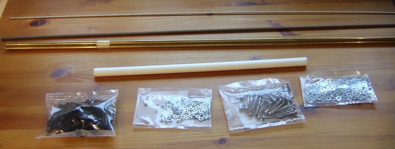
To fasten the pieces together I chose M2.5 screws and decided to tap the Perspex. The only problem there is that I have a set of large taps that go down to M3 and a set of small taps that go up to M2. I thought tapping M3 in 6mm Perspex was likely to crack it so I decided to try using the screws to cut their own thread. That was a nightmare with binding and the heads shearing.

Anyway, eventually I got it done and am quite pleased with the result.


At some point I will mount a drill vice on my X-Y table, add a laser centre finder and create a highly accurate semi-automatic drill press. Hopefully I can monitor the motor current to detect the onset of binding and make the pecking automatic.

Now I need to do some lathe work to make the moving parts, barrel and nozzle.

Friday 29 June 2007

Bob on

Here is the first RepRap part that HydraRaptor has milled :-


It is the extruder barrel clamp as shown in the previous post. As you can see it is dimensionally correct to two decimal places! It's not a fluke, the height is bob on 45.00mm as well. I have been getting pretty good accuracy with my previous milling attempts but this is astonishing.

I used a smaller end mill (2.22mm) in a collet chuck which is more accurate than the three jaw chuck I used before. The plastic is a sheet of 9mm Delrin or Acetal which I used because I read somewhere that it was a good plastic for machining. It did machine well but all the edges were left with a thin burr. This was fairly easy to remove with a fingernail.

This is not the latest version of the RepRap design but I decided it would fit my machine better. I added two more mounting holes and changed the central hole diameter to match my PTFE barrel which is 12mm rather than 10 or 16mm in the original design. The central slot is 2.5mm rather than 2mm because my bit was too big. Obviously I will have to drill the horizontal hole for the clamping bolt with a drill press.

Here is an edited video of it being made, it took around 20 minutes to make the part :-


And here is an amusing out-take if you listen to the sound :-


So having achieved perfection on this first part, things can only get worse when I attempt to make the rest of the extruder.

Sunday 22 April 2007

Too thick

I decided to order the parts to make the extruder so that they could arrive while I was writing the firmware. The official RepRap design I am working to is here. Forrest Higgs has a simpler design here but as I have a lathe and I don't have a blowtorch I decided to stick with Adrian Bower's original for my first attempt.

I got a lot of the mechanical parts from Farnell and was most impressed with their free next day delivery.


Some of the part numbers had gone obsolete, mainly due to ROHS, so I made the following substitutions :-

Description

Original

Substitute

Steel M5 Studding517343517409
Steel M3 Nuts7587968861250
Steel M3 Washers1496878861447
Steel 25mm M3 cap screws 1001658838887

10mm PTFE rod was out of stock but I found a cheap source of 12mm rod on eBay at Fantastic Plastic.

I also ordered a 5Kg reel of HDPE filament to get started with. It cost £85 including shipping. I plan to recycle milk bottles eventually but that will require a grinder. A four pint milk bottle weighs about 25g which makes them worth about 42p each. They must cost a lot less than that to make so the implication is that this stuff, sold as plastic welding rod, is overpriced.


The reel is a bit big and heavy to mount on the machine so I will probably have to re-spool it somehow.

It is a good job that I bought the filament before I made the extruder. The instructions specify to drill out the barrel to 3mm but my filament measures 3.2mm! I have ordered a 3.3mm drill from www.toolfastdirect.co.uk.

I also bought some nichrome wire to make the heater and some J-B Weld to attach it to the barrel and provide the electrical insulation and thermal coupling.


This stuff is rated up to 600°F. It is a departure from the original design which uses PTFE tape so it will be a bit experimental. I am hoping the thermal coupling will be good enough to allow me to use the resistance of the nichrome wire to measure the temperature rather than having a separate thermistor.