We have a roller blind behind plantation shutters in our bedroom to block out the light. To get a better light seal I mounted it back to front, close to the frame of the shutters. That means the ball chain chord that raises and lowers it is a bit awkward to use as it partly behind the blind.
Some blinds are geared, so that the pulling force required is less, but ours isn't. It is six foot long and I also added some steel balls to the tube that runs along the bottom to make it hang straighter. Therefore it needs quite a strong pull to raise it, so I always had a plan in the back of my mind to automate it and in August I finally started working on a design.
I have a random collection of gearmotors, so I pulled out one that seemed about the right speed and torque and printed a pulley to mesh with the ball chain and fit the shaft.
Short Heatfit inserts that I bought from Stefan at CNC Kitchen are great for printed gears and pulleys.
A quick test with a battery showed it easily had enough torque to raise the blind, taking only about 200mA at 12V, but the ball chain likes to jump out of the pulley. It would need an impractical amount of tension on the chain to keep it in, pretty obvious really given the shape of the pulley teeth.
My solution was to trap the chain between two such pulleys and use the second to drive a threaded shaft with a nut that slides along it and triggers limit switches. The up limit switch is adjustable on a slide mount to fine tune the opened stopping position. The down switch is fixed but I can adjust the idler pulley on the shaft to adjust that limit first.
My original plan was to use 6mm studding in 6mm bearings but I found that it was a very loose fit, so I use 8mm studding and turned shoulders on each end to fit the bearings with my CNC lathe. I used a collet in the spindle nose to avoid marring the thread.
I tested this with a two way / two pole toggle switch to set the motor direction and the limit switches wired in series with diodes to bypass them, so that the motor can only back away from either switch once triggered. I mounted it to the wall with a printed bracket and was able to test the mechanism worked mechanically and seemed reliable.
For the electronics I decided to use an ESP8266 module running Tasmota firmware and control it from my Home Assistant server that runs on a Raspberry Pi MK4. In Home Assistant the blind just looks like two switches, open and close. I set up automations to open it at 8 AM and close it at sunset. Tasmota is configured with two interlocked relay outputs with timeouts and two buttons for manual operation.
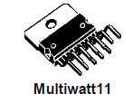
To drive the motor I had an L6203 full bridge driver chip lying around from RepRap days but I can't even remember where it came from. It's rated to 3A, so overkill in this application but I haven't had any use for it in about 14 years, so I thought I might as well use it up. The only problem was its package is a Multiwatt11 that doesn't have its pins on a 0.1" grid. I found I could fit it on a perfboard at 45° but it was looking like the electronics were going to be embarrassingly large compared to the mechanism.
Around the time I was thinking about this a member of the marketing department of PCBWay coincidentally left a message on my blog offering free PCBs in return for a review, so I decided to take them up on their offer and use a PCB to make the electronics much smaller than I could make it on perfboard.
It is about 10 years since I last designed a PCB. For one off projects I normally just scribble a schematic on paper and then use perfboard, or for mains projects I use Veroboard and remove all the unused tracks to get enough creepage clearance. It is a lot quicker than designing a PCB with CAD and getting it manufactured and shipped but most of that is waiting time. So PCBs are worth while for more complex projects or ones like this where I might need more than one.
I downloaded the latest version of KiCad, which was more than 1GB! It must have changed a lot since I last used it but seemed fairly easy to use.
It is powered by a separate 12V power supply, so the cable to the window is just figure of 8 flex and it actually fitted through a gap under the shutter's frame. A tiny buck regulator from AliExpress provides 3.3V for the ESP-12F module.
The limit switches cut the inputs to the H-bridge, so it doesn't rely on the firmware to not crash the blind. In fact, the Tasmota firmware just turns the outputs on for a fixed time that is just a bit longer than it takes to open the blind, about 30 seconds.
I thought it would be a good idea for the state of the blind to be discoverable remotely, so I used the normally open contact of the limit switches to pull two spare ports low. This was a mistake however because the GPIO2 port is connected to the blue LED on the ESP12-F module and is defined as an output, at least during start up. As these connections actually allow the firmware to crash the blind I decided to not connect them and two pin connectors could be used.
The buttons allow manual control of the blind. Pressing once starts the blind moving in the specified direction and pressing again stops it, so you can manually position the blind anywhere on its travel.
The programming connector is only needed once to load the Tasmota firmware because it can be updated over the air after that. So I don't solder it to the board and in fact there isn't room for it in the case.
The PCB design is an odd mix of through hole and surface mount because those are the parts that I had to hand.
Because I wasn't paying for it I used four layers to simplify the routing. The inner layers are ground and 12V.
I also went for a routed outline because space was so limited that I needed a cut-out in the corner to miss the limit switch. I also only had space for one screw hole, so I printed rails in the case to hold the left side and the front right corner, so rounded corners make it easier to slide into place.
This is how tight the packaging got:
I modelled the board in OpenSCAD because the 3D model from KiCad didn't have the switch positions at the correct height from the board. I could only import it as an STL file whereas with an OpenSCAD model I can query the hole and component positions.
I extracted the component placement data from the footprint positions file that KiCad produced using a python script. This needs a lot more work to make it general though because through hole PCB footprints have the origin on pin one, whereas NopSCADlib has the origin in the centre.
I did all this modelling and the case design while the boards were being manufactured by PCBWay.
I uploaded the design to PCBWay on the 12th of September and impressively they were dispatched on the 15th. The quoted build time was 4-5 days. I really liked the way the website shows you which stage they are at in the process as they progress. Four layers involve extra steps.
Clicking on the "View Details" links shows videos explaining each process step.
I also ordered a solder paste stencil for the surface mount parts and this was made as the last step. I expected it to be made in parallel but it didn't add much to the time as it seems to a be fast process.
The package was picked up in Shenzhen by FedEx on the 16th and delivered in the UK on the 20th, so only 8 days from order to delivery. The minimum order was five PCBs but I actually received six. I think probably they make an extra one in case one fails the quality checks but if they all pass they send you it. I vaguely remember that used to happen sometimes when we ordered prototype PCBs at work.
The PCBs are great quality. All the features are well aligned and the outline was very accurate as it fitted my 3D printed case perfectly.
The solder stencil worked well. I forgot that the apertures might need to be smaller than the pads, depending on the stencil thickness, to get the correct amount of solder paste. I just used the default file exported from KiCad and it seemed to give the correct amount of solder.
Here it is populated:
I chose a white solder mask to match the white PLA I used to print the case in case any of it was visible but that wasn't really necessary, green would have been fine.
I used a T-962 reflow oven to solder the surface mount components. It was the first time I had used it since buying it from Elektor a year ago, so I had to apply the upgrades detailed here:
This was replacing the masking tape with Kapton tape, adding a cold junction sensor for the thermocouples and replacing the firmware with an open source version.
I used leaded Chip Quik solder paste on the default oven profile for leaded solder and it worked great without any calibration. I mainly use leaded solder at home because it gives better results. In this case it has the advantage of not reflowing the internal parts of the ESP-12F module, which I assume uses lead free solder.
Here is the finished unit installed. I used white PLA, so hopefully it wont melt in the summer sun.
Flushed with success of this project, my wife wanted me to automate some curtains to keep the house warmer in winter. It was a race against time to get it working before our last holiday.
The gearmotor I used (Nidec GMAG 404 327) was nice because the motor has a transorb mounted on the armature to stop the back EMF from the coils causing sparks, which generate wide band RF interference. I looked it up and found out it now costs £162.36 from RS components, so I looked for a cheaper alternative for the curtains.
I found this DF-ROBOT FIT0492-A from PiHut for £11.40:
It was a challenge to make a gear_motor class in NopSCADlib that can draw both but I manged to do it, with a lot of parameters.
So it is possible to make the blind controller with the cheaper motor, although making the design handle both motors was also tricky because the clash avoiding constraints are different for each motor because their shapes are so different.
I designed a curtain puller around this new motor.
It clamps around the curtain pole, which has a hole drilled through it for the shaft. A length of picture cord goes from one bobbin, around the idler pulley clamped to the other end of the pole and back again to the other bobbin. The curtain rings at the open ends of the curtains are each attached to the forward or return cord so that they move in opposite directions.
The motor shaft has a printed spur gear to drive the threaded rod which activates the limit switches. It also acts as a coupler for an extension shaft to drive the bobbins.
It nearly worked but I ran out of time to finish it before going on holiday. I couldn't get enough grip with the 3mm grub screws because the heads would strip first. I need to replace them with M4 to get more grip. Hopefully it will work then, with perhaps some guides to stop the cords tangling.
I built 12V power supplies using some potted modules cased in a short piece of aluminium box section for fire safety.
To turn the module into a PSU you need to add a mains filter, a transorb and fuse to the AC end and a couple of filter capacitors to the DC end.
In summary, I populated three of the PCBs and they all worked first time. The PCBs were only \$25.97 for 5 pieces in 4-5 days, if I had been paying for them. The solder mask was \$10 in 1-2 days. FedEx shipping \$22.89.
Now that I have got my reflow oven set up I will make more use of PCBs and SMT parts. PCBWay make it very quick and easy to get good quality PCBs for a good price. They also offer PCB assembly, CNC machining, sheet metal fabrication, 3D printing and injection moulding but I haven't explored those. Hopefully I can do my own 3D printing!
The XY table boasts Hall effect limit switches with a repeatability of ±2.5 μm so I should have no problem getting a repeatable homing position to the nearest 6 μm step. They do however have quite a lot of hysteresis and activate some distance from the actual physical end stop. In my first cut of the code the homing routine steps quickly until it sees the negative limit and then steps slowly forward until it sees the limit go away. It sets the position at this point and then ignores the limit from then on so it can achieve the full range of travel. I am not sure whether both positive and negative edges of the limit signal have the same accuracy. I will get more idea when I write the shaft encoder software. These have an index pulse so, no matter how inaccurate the limit switch is, I will be able to get an absolute fix on the position to within one shaft encoder step, which is the same as one stepper microstep.
I haven't used the positive limits yet and I can't think of a reason for needing them except for possibly an automated self-test. I will use the shaft encoders to check that the table is where I think it should be and halt if I find a significant discrepancy. That would indicate a firmware bug, tool crash or hardware failure.
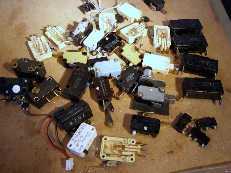
The z-axis did not come with limit switches so I had to improvise. I wanted repeatability to within one half step, i.e. 50 μm. The software knows what the shaft position modulo 8 is because it knows the phase pattern applied to the motor. That means it only needs a limit switch with repeatability better than 0.4 mm. I decided to try a micro switch to see if I could find one good enough. As you can see I have managed to amass quite an extensive collection!
I picked one of the small ones on the bottom right and it seems to do the trick. Again it has significant hysteresis as one would expect. My homing routine steps upwards at speed until it activates the switch and then steps down slowly until the switch opens again. At this point I AND the motor position with 7.
Once the homing was sorted out I was ready to test the accuracy.
Although I am fortunate enough to have a project room which is nearly 3m by 4m, as you can see it almost completely full of junk.
The large glass fronted MDF box on the far left next to HydraRaptor is a 400 CD jukebox that I designed and made in 1990. I used it for about 10 years until the CD player's laser wore out. At that point I ripped all the discs and stored them on my PC as mp3s. I haven't used it since but I could never bring myself to dismantle it as it is probably the best thing I have ever made. However, this week I got fed up of not having enough work space so I decided it had to go.
This is what it looked like. It had a sealed glass door on the front which is hard to photograph.
Here it is with the door open.
The discs were stacked 10 high on wooden pegs arranged in semi circles of six on seven shelves, i.e. 42 sites. The bottom shelf had a hole in it above the open CD player drawer and an empty peg used to store the next disc to be played.
That left 40 pegs of ten discs giving a maximum capacity of 400 discs. Worst case, to play a disc at the bottom of a peg, involved moving the nine discs above it to three nearest neighbours. This took about 40 seconds but as long as the playlist was not empty it would get the next disc ready and place it on the peg next to the player. It would then move the discs it had moved out of the way back onto their home pegs. Then it would hover above the player waiting for the disc being played to finish. When it did it would lift it out of the drawer and stash it on an the adjacent peg. It would then insert the new disc and while that was playing it would return the previous disc to the top of its home peg. That way the most popular discs tended to be at the top of their pegs for fast access.
The discs were moved by a robotic arm with a rubber suction cup on the end made out of a toy dart.
This was moved radially by a stepper motor with a gear box. It was attached to a trolley on steel rails which was moved vertically by a toothed timing belt driven by a large 12V DC motor with a gear box. As you can see the end of the arm has three micro switches. The left hand one was used during initialisation to find the home position of the arm. The other two were just for safety. The vertical motor is so powerful it could easily snap the arm off so I wired the limit switches in series with the motor so if the software crashed and left the motor running it would do no damage.
The arm is actually made of two pieces of perspex clamped together at the hub. When the arm descends onto a disc the top piece bends way from the bottom piece and a pair of switch contacts between them part. Again this was in series with motor for safety.
Here is a view of the electronics shelf after I removed the top :-
On the far left is a mains modem which allowed my PC upstairs to communicate with it when it was in its original home in an under stairs cupboard.
Next to that is a small switch mode PSU which powered everything.
In the middle is an aquarium pump which I used to generate the vacuum to lift the discs. I converted it from blowing to sucking by sealing the case and connecting a pipe to the air inlet underneath.
On the right is the controller :-
This is a Motorola MC6809 microprocessor with 32K battery backed RAM, 32K EPROM, a timer, a UART and two PIAs. Nowadays this would be a single chip. Here are the circuits, no free ECAD programs in those days :-
Here is a view with the electronics removed :-
Here is a close up of the mechanics :-
The vacuum pump took a while to build up pressure and release it again so I made a solenoid operated 3 way valve to turn the suction on and off quickly.
The top circuit board is an opto detector which looked at tabs on the right hand rail to know where the shelves were. The board below it is a vacuum pressure sensor to enable it to know if it had failed to pick up or dropped a disc. That only happened during development really but it was vital to detect it otherwise it would lose track of which discs were on which pegs. Originally there was just one vacuum sensor but about twice a year I had to recalibrate it. Eventually I realised this was because the change in atmospheric pressure, due to weather, was greater than the vacuum level. I fixed it by adding a second sensor and measuring the difference between the vacuum pipe and atmospheric pressure. Not a very cost effective solution as the sensors were about £13 each.
Here is a video of it moving some discs. I had to drive it manually from the test routine as it would not run without a working CD player.
You probably will have noticed that each time it picks up a disc it pauses over the peg for a while. This was because the discs tended to stick together by suction after being pressed by the weight of the ones above. This was mainly cured by putting a small circular spot label near the centre of the disc to break the seal. The delay gave time for the second disc to drop back onto the peg if it did initially lift.
So now it is no more, but perhaps I might reuse the vacuum system and the metre long axis for some sort of pick and place machine.
Most boards I have seen using the A3977 and similar chips just have a current adjustment, with all the other values fixed. Unless you strike lucky this is not going to allow accurate microstepping because the off time and PFD need to be adjusted to suit the motor and supply voltage.
A while ago Zach sent me samples of the prototype V3 stepper controller kits and the NEMA17 motors used on the MakerBot. I made up the board using my SMT oven (pizza oven controlled by HydraRaptor, more on that later).
It works well, but the initial component values are not optimum for the motor, so I decided to make a test bench from the older prototype board that I have been experimenting with. I RepRapped a chassis for it with a panel to mount some switches to vary the timing components.
The chassis is one of the biggest parts I have made, not in volume, but in overall expanse. It warped a little, despite being PLA, heated bed coming soon!
The switch on the left must be at least 20 years old and the one on the right more than 40 but they both still work fine. I save all this junk and eventually it comes in handy.
I also have potentiometers on Vref and PFD, so together with a bench PSU and a signal generator I can vary every parameter.
I knocked up a label on a 2D printer, it's so much easier to make this sort of thing than it was when the switches were born!
Zach has updated the board to have four preset potentiometers to make it fully adjustable. There are test points to allow the pots to be set to prescribed values with a multi-meter.
Vref and PFD can be measured as a voltage, but the two RT values have to be set by measuring resistance with the power off. My multimeter seems to give accurate readings of these despite them being in circuit. A good tip is to measure the resistance with both polarities and if it reads the same either way round then it is most likely the chip is not affecting the reading.
So here is a list of motors and optimised settings: -
MakerBot Kysan SKU1123029 NEMA17
This is the motor that MakerBot use for the axis drive on the Cupcake, details here. It is actually a 14V motor, so is not ideally suited to being driven from a 12V chopper drive. You normally want the motor voltage to be substantially lower than the supply.
You can't run it at its full current because the duty cycle would tend to 100%. With a fixed off-time, the on-time tends towards infinity and the frequency drops into the audio range.In practice I found the maximum current at 12V was 0.3A, any higher and the microstepping waveform was distorted on the leading edge due to the current not being able to rise fast enough.
To maintain the sinusoidal waveform at faster step rates requires the current to be lowered further, 0.25A gives a good compromise. It is not a bad idea to under run steppers anyway, otherwise they can get too hot for contact with plastic.
I used the minimum values for CT and RT, i.e. 470pF and 12K to keep the chopping frequency as high as possible, so that it is outside of the audio range. Not only is this a good idea to keep it quiet when idling, but also you want it much higher than your stepping frequency, otherwise they beat with each other.
The values give a minimum frequency of ~17kHz @ 0.3A and a maximum of ~150kHz on the lowest microstep value.17kHz is not audible to me, but younger people might be able to hear it. There is still some audible noise at the point in the cycle when both coils have similar currents and so similar high frequencies. The beat frequency, which is the difference of the two, is then in the audio range. It isn't anywhere near as loud as when the chopping is in the audio range though.
I can't see any spec for the maximum switching frequency although a couple of parameters are given at less than 50kHz. I suspect 150kHz is a bit on the high side, which would increase switching losses, but with such a low current compared to the rating of the chip I don't think it is a problem.
One problem I had initially was that the switching waveform was unstable. It had cycles with a shorter on-time than required, which let the current fall until it then did a long cycle to catch up. The long cycle gave a low frequency that was back in the audio range.
I think it was a consequence of the motor needing a very short off-time in order to be able to have the duty cycle nearly 100%. The current hardly falls during the off period, so a little noise due to ringing can trigger it to turn off too early. It is not helped by using the minimum blank time. I fixed it by putting 1uF capacitors across the sense resistors.
The PFD value is best set to 100% fast decay with this motor.
It works better with a 24V supply. The full 0.4A current can be achieved (but it gets much hotter of course) and it maintains microstepping accuracy at higher step rates than it does on 12V.
MakerBot Lin SKU4118S-62-07 NEMA17
This is the NEMA17 that MakerBot used to supply. It is at the opposite extreme compared to the one above, i.e. it is a very low voltage motor, only 2V @ 2.5A. As mentioned before, this causes a couple of issues: -
The inductance is so low that the ripple current is significant compared to the lowest current microstep, causing positional errors. OK at 2A, but gets worse with lower currents.
It is difficult to get 2.5A from the A3977 without it overheating. The PCB layout has to be very good. The datasheet recommends 2oz copper and four layers. 2A is no problem and that is the maximum with the 0.25Ω sense resistors fitted to the board.
At 2A the motor runs at about 40°C, so just about OK for use with PLA. The chip gets a lot hotter, about 77°C measured on the ground pins.
I used a value of 56K for RT and 2.1V on PFD. To some extent the optimum PFD value depends on how fast you want it to go.
Motion Control FL42STH47-1684A-01 NEMA17
This is the recommended motor for the Mendel extruder, details here. After buying a couple of these a friend pointed out that Zapp Automation do the same motor with dual shafts for about half the price!
This is a high torque motor so it is longer and heavier than the previous two NEMA17s. Electrically it is in the sweet spot for the A3977 with a 12V supply. The A3977 can easily provide the full current and the switching frequency doesn't have wild fluctuations or drop into the audio range.
When microstepped at 1.7A it gets to about 43°C but the chip only gets to 56°C.
I used 39K for RT and 0V on PFD, i.e. 100% fast decay.
I have high hopes for this motor as a replacement for the one above that is in my extruder currently. It should give me almost twice the torque and has the correct sized shaft, i.e. 5mm. The Lin and Kysan motors both have imperial shaft sizes which caught me out as I drilled the worm gear for 5mm thinking NEMA17 specified that, but it must just be the frame dimensions.
MakerBot Keling KL23H251-24-8B NEMA23
This is the motor I used on my Darwin. It has 8 wires so it can be connected in bipolar serial or parallel. Series has the advantage that the full torque can be achieved with 1.7A which is easily within the range of the A3977. Parallel has one quarter of the inductance so torque will fall off with speed four times slower. To get full torque 3.4A is needed but I found 1A was enough for the X and Y axes. I think Z needs more torque but my z-axis uses different motors so I don't know how much.
An RT value of 56K is fine for currents in the range 1-2A. PFD is best at 0v, i.e. 100% fast decay.
Having set the correct off time to suit my motor I can now micro step it with equal spaced steps, but only if I disable the mixed decay mode.
When the chopper switches off it can do it two ways. It can turn on both low side transistors. That short circuits the motor and lets the current recirculate. If the coil was a perfect inductor and the transistors perfect switches, the current would circulate forever and you would have a superconducting magnet. Real coils and transistors have some resistance, which causes the current to decay, but as these are relatively small the mode is called slow decay.
This is fine and efficient until you take the motor's back emf into account. During the rising part of the sine wave the magnet is moving towards the pole piece, so it generates a voltage that causes the current to fall faster. The on time gets longer to compensate and all is well.
On the trailing edge of the sine curve the magnet has gone past the pole piece and generates a voltage that increases the current in the coil. If it is going fast enough it can mean that the current doesn't fall at all during the slow decay period. As I showed previously that can cause a severely distorted waveform which makes the motor noisy.
The Allegro chips offer a mixed decay mode, where they switch to fast decay for part of the chopping cycle on the downward half of the sine curve. In fast decay mode one low side and one high side transistor turn on and reverse the voltage across the motor. That overcomes the BEMF and causes the current to fall much faster. It also returns current to the supply rail, which can upset some power supplies if there isn't some other load to absorb it.
Mixed decay gives a current waveform like this: -
The off time is fixed, so the current falls further making the ripple greater. If you set the percentage fast decay to give a clean waveform at your top speed, then the ripple increases at slower speeds. It is maximum when stationary, when there is no BEMF and fast decay is not required at all.
The problem is that the target current is the trip point of the comparator, so it is the peak of the chopping waveform. That means the average current is less by half the ripple current giving a positional error.
With the low inductance motor I am using, the ripple current has a large amplitude, so the error introduced when the motor is stationary is about the same as a micro step. That means the first step with fast decay is about twice as big as it should be and the last step is virtually zero.
With the A3977 I can disable fast decay and the steps are fairly even, but fast running is then distorted. The PFD setting needs to change with speed.
With the A3983 that I have used on my new extruder controller the PFD setting is fixed at 31.25%. That means I can't get evenly spaced microsteps with the NEMA17's that I have, when running slowly. Not a big problem with the extruder because I plan to gear it down 40:1, which means one micro step is only about 0.02mm. I am only using microstepping to give smooth motion rather than extra resolution.
The problem is exaggerated because not only am I using a low inductance motor, but I am also trying to run it at 1A, whereas it is rated for 2.5A. At 2.5A the off time would be about 2.5 times smaller, so the ripple would be 2.5 times less. The steps in the current waveform would be 2.5 times bigger, so the distortion would be reduced by 6.25 times. As it is about one microstep now, it would reduce to 1/6th of a microstep, so would be acceptable. The temperature rise would then be 6.25 times greater of course.
I was planning to use A3977s for my axis control though, where positional accuracy is important. I am beginning to think I will be better off just using dual H-bridges and doing the rest in software using a powerful micro with a fast ADC.
To be able to cope with a wide variety of motors you need to change the current, the off time setting and the percentage of fast decay. You also need to take the ripple current amplitude into account to control the average current, rather than the peak. All these things could be automated with a software solution.