
It worked well at first, requiring little force to extrude PLA, but got harder and harder until eventually it completely jammed. This video below shows that even with the nozzle removed and starting with a completely empty barrel I couldn't push more than about 15mm of filament through it.
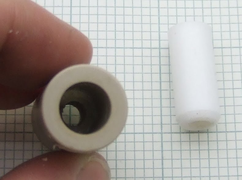
The reason was that the PTFE liner had slipped a little leaving a small gap between it and the end of the brass heater barrel.

This makes the extruder jam completely solid. The reason is that PLA goes rubbery above 50°C, so any pressure on it makes it expand width wise and grip the side of the tube. If there is a gap that it can expand into it locks the filament.
I stripped it down, cleaned it out and reassembled it with some washers to hold the PTFE down.
Brian has added a circlip to the design to solve the problem.

I haven't tested this version yet because I ran into another problem before it arrived. When I started using a heated bed for PLA the extruder jammed again. This time it was because the top end of the insulator got hotter than the glass transition of the PLA, so it swelled as it went into the insulator and jammed in the tapered entrance. There was also some leakage around the threads.

The reason it got too hot is a combination of the heated bed, the fact that I used an uninsulated heater with a large surface area, and the fact that the Mendel carriage traps the rising heat.

I decided to try out an idea I had a while ago, which is similar in intent to Brian's scheme. Instead of putting PTFE inside PEEK to stop it expanding I put it inside a 15mm copper pipe. This not only totally constrains it so it cannot swell, it also removes heat from it, shortening the transition zone. I am calling this one Plumbstruder. Here is a sketch of the layout: -

The end of the copper pipe is closed off by soldering an end cap on and then drilling it out to leave a lip to support a PEEK disk which the barrel screws into as well as into the PTFE. That means the PEEK supports the extrusion force, as in Brian's design, but I also use the thread in the PTFE as a seal rather than just having a compression joint.
The copper pipe gets hot so I coupled it to a big heatsink with a copper flange.

I turned this from a solid block of copper a friend gave me (thanks Paul). I soldered it onto the pipe and screwed it onto the heatsink.

I turned the one piece nozzle / barrel from hex stock so it has a nut shaped flange in the middle to make it easy to screw in and also gives the aluminium heater block something to tighten against.

I had to turn down the PTFE to be a tight fit inside the pipe. I was hoping to find a size where the ID of the pipe matched the OD of the PTFE. 22mm copper pipe has an ID of 20mm, so theoretically 20mm PTFE rod would fit. In practice I have found that PTFE rod is about +/- 0.5mm so, unless you were lucky, the fit would not be good enough.
Even with a big heatsink it was getting uncomfortably warm so I added a tiny fan.

I have been using this extruder on my Mendel for a few weeks and it is totally reliable, with no sign of leaking. I think that of all the extruders I have made, this one needs the least force to extrude. I can push plastic through by hand at high speed with ease. For an extruder to work I think the transition zone needs at least two of the following three attributes: short, slippery or tapered. Unfortunately a short transition zone seems to mean using a heatsink, which is not ideal for a moving head machine.
I also think a short melt zone improves the accuracy by reducing the start-stop time. In that respect this design is not ideal, although it is no worse than the standard design.


I noticed a small "crack" in the center of the last image.. Below and right of the small fan.. Is this usual for printed objects under pressure (assuming pressure from bolt)?
ReplyDeleteare layers filled in i criss-cross fasion? in order to increase antibrakeige?
//Sweden
I don't think the bolt cracked it. It is de-lamination caused by the warping stress during building. The infill is criss-crossed but that is vertical in this picture as the block is built on its side.
ReplyDeleteThe ones I sell on eBay don't have any cracks because I now build them at a higher temperature. It is quite a difficult object to print in ABS though, even on a heated bed.
this one gives me a good idea i hope i can get it to work, i will have to draw it out and see if i can build it, but i do think this is a very good idea.
ReplyDeleteMy design is based entirely on your "yet another heater hack" and so now (minus the copper sleeve) it looks almost identical however, I use a brass m6 nut on my barrel to act as a lock nut against the heater block. It just seems a little simpler than going to the trouble of turning the barrel from hex stock. Once the heater is locked against the nut you can screw the whole assembly into the ptfe no problem. I will have to give the copper sleve thing a try one day if it proves to be better.
ReplyDeleteGood use of the conductive property of these ubiquitous parts (I already have them)! I like this design. It's also nice to not need PEEK anymore, which is quite expensive and you usually have to buy larger quantities.
ReplyDeleteIf you don't have and end-cap, you can deform and cut the copper very easily, it won't be as pretty but would still work.
Well there is still a small PEEK disc to support the barrel and keep the PTFE constrained. I have put metal around PTFE before only to have it creep lengthways.
ReplyDeleteNormally the PTFE gets longer as it warms up, messing up the z-calibration. With this design it can't expand, so if anything it must make the hole down the middle smaller and tighten the thread.
When a pipe is cut with a pipe cutter you do get a lip on the end. I could have used that instead of the end cap, but I did not trust it to not allow the PEEK to move as the PTFE tries to expand. Potentially the pressure could be quite high.
To get rid of the heatsink I could put a 22mm pipe around the outside and pump water through it!
I think I can probably get away with less thread in the PTFE and still get a seal. If I could reduce it to 5mm that should halve the heat loss I think and also reduce the melt zone.
Could the PEEK disk be replaced with just an m6 nut? That would relieve stress even better than the disk and they are readily available. Or am I overlooking something?
ReplyDeleteIt needs to be a thermal insulator and also it needs to completely cover the end of the PTFE otherwise it will creep round it.
ReplyDeleteNophead,
ReplyDeleteWould you mind describing the nozzle dimensions (I assume they are similar to your previous nozzles). I like the idea of this design as it seems to be a good progressive step on the experiments you have been conducting. I'm in the processing of acquiring materials for my first extruder and am leaning towards your design's as they are the best documented with real experimental results.
Thanks,
Craig
Out of curiosity, why does it need to be a thermal insulator? Wouldn't a metal disk tapped with an m6 hole serve as a heat sink to disperse heat at the top of the barrel (assuming the disk also contacts the copper cap), as well as relieve the stress of the PTFE?
ReplyDeleteIt needs to be a good insulator because the barrel is at 240C and the copper pipe about 40C. You don't want to cool the top of the barrel because brass is a good conductor so it would need a lot of heater power and the resulting long thermal gradient in the barrel would make the plastic viscous and very hard to move. With this design the thermal transition, where the plastic is viscous, is in the PTFE just above the barrel.
ReplyDeleteExcellent, I'm learning :P. Thank you. I just need to find a less expensive source of PEEK I guess
ReplyDeleteExcellent post as always. Reading through your comments (and extruder history) I am intrigued by the idea of water cooling and have sketched up an idea using a one piece barrel, water jacket, small radiator and aquarium pump.
ReplyDeleteDo you think it's really feasible? I have no idea as to how much water volume would be necessary or required flow rate but it could be interesting to test out. I think it would be really great if we could get rid of the PTFE/PEEK insulator and their corresponding problems with expansion, etc.
Hopefully I'll be able weld it up with the laser by the weekend.
Honus,
ReplyDeleteYes it should be feasible. I see you made one, looks good.
If it is anything like my stainless steel extruder you will need to get rid of about 3W of heat with a temperature difference of no more than about 20C. I think you can work out the flow rate from that and the specific heat capacity of water. You will also need some sort of radiator at the other end of the pipes.
Thanks so much for the info! It was a huge help in determining the cooling system requirements.
ReplyDeleteHonus,
ReplyDeleteThere are various tiny radiators and radiator/fan combos around on the PC watercooling sites, some of them quite reasonably priced. One cool tip I saw was using an immersible pump and putting it in the water tank, it dropped noise considerably.
--DTVZ
So did you use 22mm copper pipe or 15mm? The description has me confused, as at one point it says 15mm and another 22mm. Other rough dimensions would be useful i.e. Length of copper tube, diameter of copper top etc.
ReplyDeleteKeith,
ReplyDeleteI don't have access to the dimensions where I am this week. The diagram is to scale though and the pipe has an OD of 15mm, the barrel is M6.
If I was making another I would reduce the length of the brass barrel as much as possible. Compared to my "no compromise" solution this design oozes a lot more.
I would make the PEEK disc a bit thinner and reduce the overlap of the brass with the PTFE to about 5mm. It shouldn't matter if the thread leaks a little as the leaked plastic will freeze when it gets to the copper making a seal.
I would also use a smaller resister and consequently a smaller heater block as my "NC" design.
Whilst do various research I came across http://forums.reprap.org/read.php?14,30278 where people have been having problems with there steppers for the extruder. On your machines what extruder stepper motor are you using and are you using the standard reprap stepper driver or are you driving straight from the controller which seems to be aimed at dc motors rather than steppers
ReplyDeleteI am using the high torque NEMA17 available from Motion Control and Zapp automation with my own micro-stepping extruder controller: http://hydraraptor.blogspot.com/2009/08/time-for-new-extruder-controller.html
ReplyDeleteIf you wanted to do away with the end cap and had access to a press or lathe. A potential solution would be to anneal the copper pipe and form the end around a mandrel by pressing or spinning.
ReplyDelete@nophead: Did you have to modify the Wade's RP parts at all to fit the plumbstruder? Also, can you put up a picture showing the plumbstruder fitting, i.e. same as the last picture but angled from the bottom, please?
ReplyDeleteCraig,
ReplyDeleteNo didn't modify the extruder to fit. For details of the mounting see hydraraptor.blogspot.com/2010/07/meltdown
So to understand this clearly, you want to cool the PTFE thermal barrier but not the heater barrel. The copper sleeve sinks heat away from the PTFE.
ReplyDeleteRegarding an earlier comment about using an M6 nut instead of the PEEK part, this could be possible if you put thermal insulation between the copper sleeve and the nut. Also if the nut is steel (it's thermal conductivity is less than brass) and if it is a half height nut, I don't think the thermal conduction between the heater barrel and the nut and then to the copper jacket would be that high, because of the small contact areas. Could be wrong though...
Hi Matthew,
ReplyDeleteActually the copper has two roles. As well as keeping the PTFE cool it also constrains it in all directions, so that it cannot creep away from the brass, or change in length. As it expands quite a lot it must get very tight when hot as it has nowhere to go. This allows me to run at 255C during the first layer without any problems. It has proved to be totally reliable.
To use a nut it would need a washer with OD of the ID of the pipe above it to stop the PTFE creeping round it I think.
I am not sure how much heat a stainless steel nut resting on copper would leak compared to the PEEK. SS conducts about 100 times more than PEEK, so I think the PEEK solution would be more efficient, although I could be wrong.
Great, thanks for the feedback. I'm sure PEEK is much better, but like has been said, it can be expensive and hard to get in smaller quantities.
ReplyDeleteBTW, I find your blog extremely informative and a very important part of the open source 3D printing knowledge base. Whenever I see nophead posting in other forums, I always pay attention and never skim your posts!
Keep up the excellent work!
i want to try to build one of your extruder like this one, but i know it will have to be longer, i was wondering if you were still using it, and how it has been working for you.
ReplyDeleteYes it runs 24/7 with temperatures up to 255C and never jams or leaks. So far I have printed 42 Mendels with it.
ReplyDeleteHello,
ReplyDeleteI embarked on the adventure!
And then I came across your blog, your experiences, your observations in my opinion should greatly help the community.
I make the holes in the material "nomenclature" I have in my possession a set cruise + static switch PID
In your opinion I just use it? or it could not walk and pose problem in the console app RepRap
Thank you
The Reprap firmware will do PID control so that will be easier than using a stand alone controller.
ReplyDeleteI prefer bang-bang control because it doesn't need any tuning and gives good results with my style of heater.
Merci
ReplyDeletePour tes conseils