While making a new heater I decided to try using stranded tinned copper tails rather than the solid tinned copper wire I used previously. The idea being to put less stress on the Cerastil covering.
I started with a standard piece of 7 x 0.2 stranded copper wire and removed the insulation. I found all seven strands too bulky so I decided to see how many strands I needed to carry 2A. I found that a single strand was cool to touch at 2A but very hot at 4A. I figured two strands would be sufficient for some margin.
The fact that a strand gets hot at 4A, and in fact red hot at about 5A, got me thinking that we could just use a single strand of copper for the heater. Nichrome is expensive, not that easy to obtain, and difficult to make connections to.
I measured the resistance of a strand 52cm long as about 0.3Ω (my meter only gives one digit). The strand measured 0.17mm diameter. Calculating its resistance from the resistivity of copper I get 1.72 x 10-8 x 0.52 / (π (0.00017/2)2) = 0.39Ω.
At 4A the voltage drop was 2.6V giving a resistance of 0.65Ω and a power of 10W. The thermal coefficient of resistance is 0.0039 for copper so the calculated temperature of the wire is 20 + (0.65/0.39 - 1) / 0.0039 = 191°C. It was certainly hot enough to cut through ABS.
10W and 190°C are not far from the operating conditions of an extruder. I tried winding it on the bobbin I had made for my heater but it was about twice as long as I could accommodate. I am trying to make a very short heater at the moment so I went back to using nichrome. Also 2.6V @ 4A is too much for my current drive circuit but it would be easy to come up with a switch mode converter to drive it, or simply use the 3.3V rail of a PC PSU.
So it has definite possibilities. Making the connections would be trivial. Just start with a piece of 7 strand wire and cut it down to one apart from at the ends. Some high temperature solder would keep it neat but would not be essential. A standard heater barrel with some insulation would be about 7mm diameter so 24 turns would be required. If you keep it taught and wind it in a lathe or drill chuck you can get about 2 turns per mm with some concentration. That would easily fit the space currently allocated for the heater.
Wednesday, 31 December 2008
Saturday, 27 December 2008
Simple experiment
Inspired by Demented Chihuahua's extruder work, I repeated his experiment using what was left of my old heater. I mounted it in a 30mm M6 stainless steel washer and clamped that in a vice. I used my 0.3mm aluminium nozzle, which I counter bored with a 0.7mm drill to reduce the depth of the 0.3mm hole to about 1.5mm.

I powered the heater from a bench power supply and adjusted it manually to about the right temperature. Green ABS is handy for this because it changes colour at 260°C so you can tell when it is too hot.
I can extrude filament by pushing it by hand with moderate pressure. It comes out at 0.4mm but I should be able to stretch it back down to 0.3mm without any problems. Even with a 0.5mm nozzle I can stretch it down to 0.3mm, but I lose positional accuracy because the orifice no longer defines exactly where the plastic goes.
Originally the heater was 5mm longer, with the excess protruding beyond the half nut. I found that cutting that piece off made it easier to extrude. It was probably a relatively cool section so the plastic remained very viscous there.
When a new piece of filament is inserted into the heater it extrudes very easily. After a while some plastic flows backwards and builds at the entrance to the heater. That causes considerable extra resistance. I plan to tackle that by having a short section of PTFE at the entrance with a heatsink the other side of it. The steep gradient across the PTFE should freeze the back flow over a short distance and, being super slippery, should allow it to slide back into the heater.
Another thing I tried was forcing out the plastic using the shank of a 1/8" drill bit as a piston. The further the drill got to the end of the heater the less force was needed to push it. That confirms what I had suspected. The force to push the plastic though the long 3.5mm section of the barrel is very significant compared to the force to squeeze it through the short small hole in the nozzle. So the heater needs to be kept as short as possible. Obviously there will be a point where the extrusion rate becomes limited by the rate the plastic melts if it is too short, but I expect that is much shorter than the current set-up.
Friday, 26 December 2008
New Materials
HydraRaptor's extruder suddenly stopped working in the middle of a build a few weeks ago. I tried upping the temperature and pushing the filament with pliers but it would not budge. All that happened was the heater barrel slipped a few threads in the PTFE insulator.
It was a bit difficult to find out what was wrong because it was full of solidified plastic when cold. I unscrewed the nozzle and placed it in some acetone to dissolve the ABS. It appears that the hole in the nozzle was blocked by burnt plastic. It probably formed when I had some high temperature accidents and experiments recently.
I should have realised the nozzle was blocked, but it has never happened before. If I had then I could have just unscrewed it, cleaned it out with acetone and put it back on again. In the event pushing the heater out of the PTFE pretty much wrote it off.
Not for the first time, I decided to rob parts from the extruder I was making for my Darwin. These are all made from different materials in order to see if small improvements could be made.
The barrel is made from aluminium. It is a better thermal conductor than brass, is easier to machine being a lot softer, and is cheaper.

To make the thermistor more easily removable I mounted it in ring of aluminium with a tapped hole.

The thermistor was glued in with Cerastil H-115 and the ring was screwed onto the barrel with some heatsink compound in the thread. By adjusting the beta I was able to get the reading to agree with a thermocouple inside the barrel to within a couple of degrees. I don't know if that means the ring was at the same temperature as the middle of the barrel or if it was lower and I compensated with a beta value that is not actually the beta of the thermistor. Either way it produces the desired result.
I also made an aluminium nozzle with a 0.3mm aperture. I broke the drill bit as it went through. I am not sure if that was due to the aluminium snatching more than brass does, or me being careless. I have broken loads of small drills recently and blunted some bigger ones by accidentally drilling with my lathe in reverse!

The picture also shows where the thermistor ring mounts.
Another modification I made was to put a PTFE cap over the nozzle.

This has two benefits: -

Another new material I used was Polyetheretherketone (PEEK) instead of PTFE for the thermal break. This has similar insulating properties to PTFE and a slightly better working temperature range. It machines well but forms burs very readily.
I found it much sturdier at working temperature, I don't need a pipe clip to stop the barrel popping out now, but I think it may be a bit harder to push molten plastic through, being less slippery.

The other thing I changed was I used insulated nichrome. When using bare nichrome I have to put down a thin layer of Cerastil to insulate the barrel, leave it to set, then wind the heater and cover it with more Cerastil. That makes it a two day job. By using insulated nichrome I can just wind it straight on the barrel and then cover. But what I didn't think about was that I normally make the soldered connections under the Cerastil, which I could not do this way. All in all I think bare nichrome is best as it makes a much neater job. Here is the previous heater that I made way back in March :-

So after all these "improvements" how did the new extruder perform?

Not very well! I tried it with green ABS first but could not get it to extrude reliably. I swapped the nozzle for my previous 0.5mm brass one and that got it working.
I then switched to some plain ABS that I bought a while ago but have not been able to use because it is very oval. It was too wide for my previous extruder. This extruder has a 3.5mm bore so it should easily fit but I could not get it to work reliably. It takes an enormous force to push it into the extruder. I am not entirely sure why. If I pull it out and push some green in I can extrude the plain that is left in the barrel easily so it isn't any harder to push it through the nozzle but it is to push it into the heater.
Since I foolishly changed every material at the same time it is hard to evaluate which things are better and which are worse. I have recently formed the opinion that the extruder design is far from optimum. I think we need a much sharper thermal gradient and a shorter heater barrel. I think a lot of force is wasted pushing slightly softened plastic down the thermal break.
My next attempt will have a very short thermal break with a heatsink at the cold side. I will also make it easier to strip down and reassemble. A problem with the current design is that once the heater barrel is screwed in and full of plastic it is hard to remove it.
It was a bit difficult to find out what was wrong because it was full of solidified plastic when cold. I unscrewed the nozzle and placed it in some acetone to dissolve the ABS. It appears that the hole in the nozzle was blocked by burnt plastic. It probably formed when I had some high temperature accidents and experiments recently.
I should have realised the nozzle was blocked, but it has never happened before. If I had then I could have just unscrewed it, cleaned it out with acetone and put it back on again. In the event pushing the heater out of the PTFE pretty much wrote it off.
Not for the first time, I decided to rob parts from the extruder I was making for my Darwin. These are all made from different materials in order to see if small improvements could be made.
The barrel is made from aluminium. It is a better thermal conductor than brass, is easier to machine being a lot softer, and is cheaper.

To make the thermistor more easily removable I mounted it in ring of aluminium with a tapped hole.

The thermistor was glued in with Cerastil H-115 and the ring was screwed onto the barrel with some heatsink compound in the thread. By adjusting the beta I was able to get the reading to agree with a thermocouple inside the barrel to within a couple of degrees. I don't know if that means the ring was at the same temperature as the middle of the barrel or if it was lower and I compensated with a beta value that is not actually the beta of the thermistor. Either way it produces the desired result.
I also made an aluminium nozzle with a 0.3mm aperture. I broke the drill bit as it went through. I am not sure if that was due to the aluminium snatching more than brass does, or me being careless. I have broken loads of small drills recently and blunted some bigger ones by accidentally drilling with my lathe in reverse!

The picture also shows where the thermistor ring mounts.
Another modification I made was to put a PTFE cap over the nozzle.

This has two benefits: -
- It is a good insulator so it helps to keep the nozzle warm.
- Being non-stick, and also cooler than the nozzle surface, it stops filament from sticking to it. I use a brush to wipe the nozzle. This works well with HDPE but ABS tends to curl upwards and stick. Since I added this cap the nozzle wipe has worked 100%. It remains to be seen if it works with PCL and PLA.

Another new material I used was Polyetheretherketone (PEEK) instead of PTFE for the thermal break. This has similar insulating properties to PTFE and a slightly better working temperature range. It machines well but forms burs very readily.
I found it much sturdier at working temperature, I don't need a pipe clip to stop the barrel popping out now, but I think it may be a bit harder to push molten plastic through, being less slippery.

The other thing I changed was I used insulated nichrome. When using bare nichrome I have to put down a thin layer of Cerastil to insulate the barrel, leave it to set, then wind the heater and cover it with more Cerastil. That makes it a two day job. By using insulated nichrome I can just wind it straight on the barrel and then cover. But what I didn't think about was that I normally make the soldered connections under the Cerastil, which I could not do this way. All in all I think bare nichrome is best as it makes a much neater job. Here is the previous heater that I made way back in March :-

So after all these "improvements" how did the new extruder perform?

Not very well! I tried it with green ABS first but could not get it to extrude reliably. I swapped the nozzle for my previous 0.5mm brass one and that got it working.
I then switched to some plain ABS that I bought a while ago but have not been able to use because it is very oval. It was too wide for my previous extruder. This extruder has a 3.5mm bore so it should easily fit but I could not get it to work reliably. It takes an enormous force to push it into the extruder. I am not entirely sure why. If I pull it out and push some green in I can extrude the plain that is left in the barrel easily so it isn't any harder to push it through the nozzle but it is to push it into the heater.
Since I foolishly changed every material at the same time it is hard to evaluate which things are better and which are worse. I have recently formed the opinion that the extruder design is far from optimum. I think we need a much sharper thermal gradient and a shorter heater barrel. I think a lot of force is wasted pushing slightly softened plastic down the thermal break.
My next attempt will have a very short thermal break with a heatsink at the cold side. I will also make it easier to strip down and reassemble. A problem with the current design is that once the heater barrel is screwed in and full of plastic it is hard to remove it.
Sunday, 21 December 2008
Sticking point
sid, who is a regular contributor to the RepRap forums, had an idea to get a soldering iron manufacturer to make a heater barrel assembly for RepRap. He approached a Chinese company with a specification and they sent him some prototypes. He forwarded one to me for testing. It appears that they ignored his specification and just sent a standard de-soldering iron element. Nevertheless it is a nice unit and looks eminently usable.

It has a tube running through the middle with an internal diameter a shade over 3mm. Ideally it needs to be about 3.5mm to cope with the worst filament I have encountered. My green ABS, being a little undersized, fits down it easily.
The heater has a cold resistance of 1.3Ω but, unlike nichrome, it has a big temperature coefficient, so its resistance increases significantly at it gets hot. It appears that it is a 12V 50W heater. We can drive this with PWM using a MOSFET provided the PSU can handle 9A peaks on the 12V rail in addition to what the steppers take, a tall ask. An inductor and diode could be used to reduce the peak current.
The other two wires are a type-E thermocouple. Unfortunately the thermocouple sensor board that Zach designed using the AD595 is for the more common type-K thermocouples. It can be recalibrated for type-E by adding extra resistors. However, the AD595 is an expensive chip because it is factory trimmed for accuracy. By the time you add external components the convenience and accuracy is lost so you might as well just use a cheap op-amp and a micro with an internal temperature sensor for the ice point compensation. E.g. the MSP430F2012 that I use for my extruder controller is a lot cheaper solution than the AD595 and can control the heater and motor as well.
To test the heater I clamped it by the mounting flange in a vice and hooked it up to a bench power supply. I measured the internal thermocouple's output with a millivoltmeter and also inserted a 3mm rod type-K thermcouple down the barrel. Here are the results: -
The temperature column is as measured with my type-K thermocouple towards the nozzle end of the barrel. The calculated temp column is assuming 68μV/°C from the type-E thermocouple and a cold junction temperature of 20°C. There is a big temperature gradient along the barrel so the thermocouple reading depends on where it is placed.
As you can see we only need about 5V to drive the heater. The current would start at 3.8A and fall to 2A as it warmed up. This would be kinder to the PSU and safer than using 12V, but 12V would give a much faster warm up time. I expect something better than bang-bang control would then be needed to avoid massive overshoot.
When running horizontally the inlet tube stays cold and the mounting flange is just too hot to hold so it would be ideal for mounting to ABS or HDPE. This is because the barrel appears to be stainless steel, which is a very poor conductor of heat. The element must be towards the bottom so there is a continuous thermal gradient along the barrel.
The nozzle that came with it is made from copper with some type of plating. It had a hole to mate with the tube that sticks out of the end of the heater but it did not go all the way through. In fact it could not, as the tip comes to a fine point. I suspect this is a soldering iron bit that has been drilled out to fit.


I attempted to drill a 0.5mm hole through it but it just snapped the drill. Even drilling a 1mm hole snapped the drill. In the end I drilled a 2mm hole, but the drill bent and came out the side. I think it needed to be sharper for copper. Finally, I cut the point off and filled the 2mm hole with high temperature solder. That is soft enough to easily drill a 0.5mm hole through. It melts at 300°C so should hold up.

The heat damage is where I heated it up with a blow torch in an attempt to remove the broken drill bits. Copper expands a lot more than steel. That did not work so I tried to get it red hot to soften the drill bits so I could drill them away. I failed to get it red hot but I did melt the plating.
The shape is not ideal for making objects but it is good enough to see if I can extrude. In fact it extrudes well. I was able to push a piece of ABS through it easily by hand and it extruded at a very good rate.

The bit/nozzle is clamped on to the end of the barrel by an outer stainless steel sleeve tightened up by a threaded ring at the cold end. I was worried it would leak under extrusion pressure without some sealing. When I stripped it down I found it did leak a little but didn't get far. I suspect it freezes when it meets the outer sleeve.

So apart from the bore being a little too small this seems like a perfect solution: -
The reason the original extruder design does not have this problem is that the thermal gradient is in the PTFE. It is much shorter so the problem region that is soft but not molten is a lot shorter and the walls are very slippery so it can still be shifted.
I can't think of a solution to this problem. You could make the internal tube out of copper but then the top end would be hot so you would need a PTFE thermal break again. Also it would not be an off the shelf product, it would be custom to RepRap. Perhaps a taper at the problem region could stop it sticking.
The next extruder I am building has an aluminium barrel and nozzle and a PEEK thermal break. It won't suffer from this problem at least.

It has a tube running through the middle with an internal diameter a shade over 3mm. Ideally it needs to be about 3.5mm to cope with the worst filament I have encountered. My green ABS, being a little undersized, fits down it easily.
The heater has a cold resistance of 1.3Ω but, unlike nichrome, it has a big temperature coefficient, so its resistance increases significantly at it gets hot. It appears that it is a 12V 50W heater. We can drive this with PWM using a MOSFET provided the PSU can handle 9A peaks on the 12V rail in addition to what the steppers take, a tall ask. An inductor and diode could be used to reduce the peak current.
The other two wires are a type-E thermocouple. Unfortunately the thermocouple sensor board that Zach designed using the AD595 is for the more common type-K thermocouples. It can be recalibrated for type-E by adding extra resistors. However, the AD595 is an expensive chip because it is factory trimmed for accuracy. By the time you add external components the convenience and accuracy is lost so you might as well just use a cheap op-amp and a micro with an internal temperature sensor for the ice point compensation. E.g. the MSP430F2012 that I use for my extruder controller is a lot cheaper solution than the AD595 and can control the heater and motor as well.
To test the heater I clamped it by the mounting flange in a vice and hooked it up to a bench power supply. I measured the internal thermocouple's output with a millivoltmeter and also inserted a 3mm rod type-K thermcouple down the barrel. Here are the results: -
| Voltage | Current | Power | Resistance | Temperature | Thermocouple | Calculated Temp |
| 1 V | 0.75 A | 0.8 W | 1.3 R | 43 C | 1.5 mV | 42 C |
| 2 V | 1.20 A | 2.4 W | 1.7 R | 106 C | 5.6 mV | 102 C |
| 3 V | 1.55 A | 4.7 W | 1.9 R | 182 C | 9.5 mV | 160 C |
| 4 V | 1.80 A | 7.2 W | 2.2 R | 275 C | 14.5 mV | 233 C |
| 5 V | 2.00 A | 10.0 W | 2.5 R | 357 C | 20.0 mV | 314 C |
The temperature column is as measured with my type-K thermocouple towards the nozzle end of the barrel. The calculated temp column is assuming 68μV/°C from the type-E thermocouple and a cold junction temperature of 20°C. There is a big temperature gradient along the barrel so the thermocouple reading depends on where it is placed.
As you can see we only need about 5V to drive the heater. The current would start at 3.8A and fall to 2A as it warmed up. This would be kinder to the PSU and safer than using 12V, but 12V would give a much faster warm up time. I expect something better than bang-bang control would then be needed to avoid massive overshoot.
When running horizontally the inlet tube stays cold and the mounting flange is just too hot to hold so it would be ideal for mounting to ABS or HDPE. This is because the barrel appears to be stainless steel, which is a very poor conductor of heat. The element must be towards the bottom so there is a continuous thermal gradient along the barrel.
The nozzle that came with it is made from copper with some type of plating. It had a hole to mate with the tube that sticks out of the end of the heater but it did not go all the way through. In fact it could not, as the tip comes to a fine point. I suspect this is a soldering iron bit that has been drilled out to fit.


I attempted to drill a 0.5mm hole through it but it just snapped the drill. Even drilling a 1mm hole snapped the drill. In the end I drilled a 2mm hole, but the drill bent and came out the side. I think it needed to be sharper for copper. Finally, I cut the point off and filled the 2mm hole with high temperature solder. That is soft enough to easily drill a 0.5mm hole through. It melts at 300°C so should hold up.

The heat damage is where I heated it up with a blow torch in an attempt to remove the broken drill bits. Copper expands a lot more than steel. That did not work so I tried to get it red hot to soften the drill bits so I could drill them away. I failed to get it red hot but I did melt the plating.
The shape is not ideal for making objects but it is good enough to see if I can extrude. In fact it extrudes well. I was able to push a piece of ABS through it easily by hand and it extruded at a very good rate.

The bit/nozzle is clamped on to the end of the barrel by an outer stainless steel sleeve tightened up by a threaded ring at the cold end. I was worried it would leak under extrusion pressure without some sealing. When I stripped it down I found it did leak a little but didn't get far. I suspect it freezes when it meets the outer sleeve.

So apart from the bore being a little too small this seems like a perfect solution: -
- It needs no construction apart from drilling the nozzle.
- It is mechanically sturdy.
- It should be very durable; soldering irons last a lifetime and they run at higher temperatures.
- It is cold enough to mount with plastic without any insulation. It does after all in a soldering iron although that is probably a thermoset plastic.
- The nozzle can be easily removed and replaced.
The reason the original extruder design does not have this problem is that the thermal gradient is in the PTFE. It is much shorter so the problem region that is soft but not molten is a lot shorter and the walls are very slippery so it can still be shifted.
I can't think of a solution to this problem. You could make the internal tube out of copper but then the top end would be hot so you would need a PTFE thermal break again. Also it would not be an off the shelf product, it would be custom to RepRap. Perhaps a taper at the problem region could stop it sticking.
The next extruder I am building has an aluminium barrel and nozzle and a PEEK thermal break. It won't suffer from this problem at least.
Sunday, 30 November 2008
Suppression
Some time ago I blogged that the GM3 gearmotor generates a lot of RFI, which was interfering with TV reception in our house and corrupting I2C comms on HydraRaptor. I designed a simple suppressor that fixed the problem, details here.


Recently Zach Smith designed a nice little PCB version of it and produced a kit. He gave me a sample to test. Here it is installed on a GM3: -

To test it I wired a GM3 with no suppressor to a bench power supply with a pair of jumper cables about 30cm long. I viewed the noise on both motor terminals with a scope grounded at the PSU. This is what it looks like in the time domain.

It is massively noisy producing about 50V pk-pk. And here is the spectrum in the frequency domain: -

Although this is the 12V version of the motor it looks similar to the 6V version I tested before.
I repeated the same test with the suppressor fitted, measuring the voltage at the terminals of the suppressor.

The noise is vastly reduced, now only about 700mV pk-pk.

The spectrum is reduced drastically as well: -

Compared to my Vero board version, tested under the same conditions, it seems to work a bit better, but that could be down to variations between motors.
So the kit version works well and also gives convenient screw terminals or 0.1" header robustly anchored to the motor.
Tuesday, 25 November 2008
Dodecahedron
I fancied making a dodecahedron, an object with twelve pentagonal faces. It is an interesting shape and, as the sides slope at ~26°C, it can be made without support material. I searched the web for a 3D model for some time but could not find one. I also searched for how to model one in CoCreate, as it wasn't immediately obvious to me. That came up blank as well so I had to figure it out myself.
I started with a construction circle and divided it into 5 sectors with construction lines 72° apart. I joined the intersections to make the base pentagon.

I then extruded that to a height equal to the circle radius and with a draft angle of -26.56505°. This is the dihedral angle (2arctan((1+√5)/2)) minus 90°. That makes the base of the object and the first line of vertices above it.

I then made a new workplane on one of the partial faces. I projected the face onto the workplane and then added a construction circle through three of the points. A vertical line from the centre gives the missing fifth vertex where it meets the circle.

I then join the vertices to make the pentagon, extrude it inwards (negative) by the circle radius with the same negative draft angle.

That operation has generated two partial faces with all five vertices. I construct the pentagons from the vertices and extrude inwards by the circle radius until the shape is complete. A total of eight extrusions are required.

I then shelled the object to 2mm to make it hollow. That created a second part inside, revealing that the construction does not in fact make a complete solid. If that was important one could extrude one of the faces more than half way through, with no draft angle. I just deleted the second part.

The finished item is about 2.5 times initial circle radius across opposite flats. This one was based on a 10mm radius circle.

The file is available on Thingiverse.
I started with a construction circle and divided it into 5 sectors with construction lines 72° apart. I joined the intersections to make the base pentagon.

I then extruded that to a height equal to the circle radius and with a draft angle of -26.56505°. This is the dihedral angle
(2arctan((1+√5)/2)) minus 90°. That makes the base of the object and the first line of vertices above it.
I then made a new workplane on one of the partial faces. I projected the face onto the workplane and then added a construction circle through three of the points. A vertical line from the centre gives the missing fifth vertex where it meets the circle.

I then join the vertices to make the pentagon, extrude it inwards (negative) by the circle radius with the same negative draft angle.

That operation has generated two partial faces with all five vertices. I construct the pentagons from the vertices and extrude inwards by the circle radius until the shape is complete. A total of eight extrusions are required.

I then shelled the object to 2mm to make it hollow. That created a second part inside, revealing that the construction does not in fact make a complete solid. If that was important one could extrude one of the faces more than half way through, with no draft angle. I just deleted the second part.

The finished item is about 2.5 times initial circle radius across opposite flats. This one was based on a 10mm radius circle.

The file is available on Thingiverse.
Sunday, 23 November 2008
Lathe accesories
Khiraly asked me for a walk through of the lathe accessories I mentioned before, so here goes. I am no expert on lathes, I am learning as I go along. In fact, I learnt quite a lot writing this!
Cutting tools

This is an 11 piece tungsten carbide turning tool set. I had some trouble finding out exactly what each tool is intended for. This diagram, from the McMaster-Carr catalogue, gives a good idea but doesn't exactly match the shapes.

Today I noticed that each tools is stamped with a DIN standard. Googling those mainly came up with German and Scandinavian adverts for the tools, some of them charging $99 for one tool! Eventually I found a German site selling DIN standards. Putting in each number gives the title of the standard, which is the description of the tool.
So from left to right we have: -
8 would also be mounted parallel to the axis, but with the cut going across the face of the workpiece.
9 is mounted perpendicular to the axis and is driven into the work to cut it off from the stock. I hadn't realised it was a parting off tool, I have happily been using it to turn bearing lands with straight sides. I bought a thinner parting off blade, which wastes less material.

All the other tools are for mounting roughly at right angles to the axis and cutting along the outside of the workpiece.
11 has a 60° point for cutting external threads. I bought a set of gearwheels for cutting metric threads. These alter the speed of the lathe's auto feed to match the thread pitch. The procedure looks a bit complicated though, so I have stuck to using a die so far. It would be nice to be able to make large pitch ACME lead screws but that seems even more complicated.
I have had titanium nitride indexable tools recommended to me for their very long life. They have a three pointed replaceable tip. Each time a tip wears out you can rotate it until they are used up, at which point you replace it. They are quite expensive but replacement tips are not too bad.
You can also buy blank steel tools and grind them to whatever shape you want yourself.
Tools are mounted in the tool post and held down with machine screws :-

The tip of the tool must be at the same height as the centre of work. This is most easily done by aligning it against the tailstock centre. Small differences can be compensated for with the rocker under the tool by tilting it slightly. Large differences would result in the tool at the wrong angle so the other side of the post is used with a shim. The tool should be gripped as close to the working end as possible to prevent chatter.
Compound Slide
The lathe comes with a cross slide that allows you to move the tool across the workpiece and the feed screw allows motion along the axis of the lathe. To be able to cut a taper, and for cutting threads, you need to be able to move at an angle to the lathe's axis. The compound slide replaces the tool post and adds another axis of movement at any desired angle.

The next model up lathe, the CL300M, includes a compound slide, so if you take that into account the price difference is not that much. A lathe without one is quite limited, IMHO.
Drill Vice
I got a tiny quick release drill vice that fits on the cross slide to hold work for drilling or milling. Quick refers to the fact that rather than screw the vice all the way to open it, you lift a ratchet and drop it in the nearest slot for the width you want. Then you use the screw to tighten it no more than a quarter of its maximum travel.

This highlights the main compromise having the lathe, mill, drill combo. The cross slide is wider than normal for a lathe, which limits how close the tailstock can get to the chuck, but small for a milling table or a drill table. Also the height of the cross slide means that the tallest thing you can drill is not as much as you would expect from a pillar drill. If I get desperate I could remove the tailstock and cross slide, move the saddle out of the way and put a board on top of the lathe bed to drill a large object.
Tailstock Chuck
This is just a drill chuck with an MT1 Morse taper to fit into the tailstock quill. It allows you to drill into the center of the work piece. You might think holding the drill stationary and spinning the work is the same as spinning the drill and holding the work. It isn't, the former ensures the hole is exactly down the centre of the workpiece.

The chuck is exactly the same as the one the comes with the milling machine, but annoyingly that and the headstock have MT2 tapers but the tailstock is only MT1. If the tailstock was MT2 it could have shared the chucks with the milling machine, and also many other tailstock attachments, like boring heads and tap holders that only seem to go down to MT2.
Four Jaw Chuck
The lathe comes with a three jaw self-centring chuck. The jaws all move together to hold a round or hexagonal workpiece centrally (within the accuracy of the chuck). To hold a square or octagonal shaped object you need a four jaw chuck. These usually have jaws that move independently allowing / requiring objects to be centred manually. That also allows rectangular objects to be centred and you can also mount things deliberately off centre.
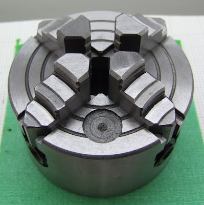
Potentially you can centre round things more accurately than you can with a three jaw chuck but it takes more time and skill.
Large, and or completely irregular shaped things can be held using a faceplate and bolts or clamps.
Milling Chuck
The drill comes with a normal three jaw drill chuck.

A collet chuck provides better centring and grip for milling. Expensive, but the sizes match a set of end mills I already had.

This also fits the headstock, so another way you can mill and drill on a lathe is by using a vertical slide.
Wiggler
This is a special chuck and a set of probes that are used for lining up the drill / mill with centre marks and edges of the workpiece.

The special chuck forms a ball and socket joint with the probe so it can swing. When you spin it in the drill chuck it rotates in a circle, but by pressing on the edge you can persuade it into a mode where it spins dead centre to axis of rotation. You use the point to line up on centre punched holes and the ball and cylinder for finding edges. The bent one is used with a dial indicator but I don't understand how or why.
Instructions for using one are here. The balls are imperial sizes, which is a pain if you are working in metric units. I don't know if you can get metric ones.
Die Holder
This allows tapping an external thread by turning the workpiece in the chuck and holding the die with the tailstock.

The bar goes in the tailstock. The tube slides over it and can be rotated part of a turn with the handle. Different size dies can be used in each end of the holder and the two adaptors allow for two larger sizes.
I could not find one to fit an MT1 tailstock, so I had to get an MT2 one plus an MT1 to MT2 adaptor.

This is far from ideal because it takes up so much of the distance between centres. I ground off the tang at the end of the taper because there is nothing to engage it on my lathe. That gives me about another 10mm. I will probably bore out the end of the die holder's bar so that it will accept an M5 bar inside it. That will allow longer threads to be tapped without weakening it too much.
One other problem with the die holder was that the set screws in it do not have pointed ends. When using split dies the middle screw should have a cone shaped point so that tightening it forces the split open, allowing an oversize thread to be cut. Tightening the outer two makes an undersized thread. When tapping something hard like stainless steel you need to start oversized and then work down.
I solved the problem by turning a point on an M5 setscrew to replace the middle screw.
I should really have made one of these, I think, rather than buying this one that is too big. It should be fairly straightforward to make on a lathe. I don't fancy turning an accurate MT1 taper but you can buy Morse tapers with a soft blank on the end for machining to a custom use.
Centres

The MT1 tailstock centre of the right came with the lathe and is known as a "dead centre" because it does not rotate. The one in the centre is a "live centre" because it has a bearing, which allows it to rotate with the work, reducing the friction. There is also a variant called a "half dead centre" which is a dead centre with half the cone cut away to allow a facing tool to get in.
I also got an MT2 dead centre to fit the headstock or my MT2 adapter.
Some good reference material: -
www.americanmachinetools.com/how_to_use_a_lathe
myweb.tiscali.co.uk/silkstone/minilathe/minilathe01
Cutting tools

This is an 11 piece tungsten carbide turning tool set. I had some trouble finding out exactly what each tool is intended for. This diagram, from the McMaster-Carr catalogue, gives a good idea but doesn't exactly match the shapes.

Today I noticed that each tools is stamped with a DIN standard. Googling those mainly came up with German and Scandinavian adverts for the tools, some of them charging $99 for one tool! Eventually I found a German site selling DIN standards. Putting in each number gives the title of the standard, which is the description of the tool.
So from left to right we have: -
- DIN 4974 R Internal side turning tools for corner work with carbide tips.
- DIN 4973 R Boring tools with carbide tips.
- DIN 4980 L Offset side turning tools with carbide tips.
- DIN 4980 R As above but right handed.
- DIN 4978 R Offset turning tools for corner work with carbide tips.
- DIN 4971 R Straight turning tools with carbide tips.
- DIN 4972 R Bent turning tools with carbide tips.
- DIN 4977 R Offset face turning tools with carbide tips.
- DIN 4981 R Parting-off tools with carbide tips.
- DIN 4976 Wide face square nose tools with carbide tips.
- DIN 4975 Pointed straight turning tools with carbide tips.
8 would also be mounted parallel to the axis, but with the cut going across the face of the workpiece.
9 is mounted perpendicular to the axis and is driven into the work to cut it off from the stock. I hadn't realised it was a parting off tool, I have happily been using it to turn bearing lands with straight sides. I bought a thinner parting off blade, which wastes less material.

All the other tools are for mounting roughly at right angles to the axis and cutting along the outside of the workpiece.
11 has a 60° point for cutting external threads. I bought a set of gearwheels for cutting metric threads. These alter the speed of the lathe's auto feed to match the thread pitch. The procedure looks a bit complicated though, so I have stuck to using a die so far. It would be nice to be able to make large pitch ACME lead screws but that seems even more complicated.
I have had titanium nitride indexable tools recommended to me for their very long life. They have a three pointed replaceable tip. Each time a tip wears out you can rotate it until they are used up, at which point you replace it. They are quite expensive but replacement tips are not too bad.
You can also buy blank steel tools and grind them to whatever shape you want yourself.
Tools are mounted in the tool post and held down with machine screws :-

The tip of the tool must be at the same height as the centre of work. This is most easily done by aligning it against the tailstock centre. Small differences can be compensated for with the rocker under the tool by tilting it slightly. Large differences would result in the tool at the wrong angle so the other side of the post is used with a shim. The tool should be gripped as close to the working end as possible to prevent chatter.
Compound Slide
The lathe comes with a cross slide that allows you to move the tool across the workpiece and the feed screw allows motion along the axis of the lathe. To be able to cut a taper, and for cutting threads, you need to be able to move at an angle to the lathe's axis. The compound slide replaces the tool post and adds another axis of movement at any desired angle.

The next model up lathe, the CL300M, includes a compound slide, so if you take that into account the price difference is not that much. A lathe without one is quite limited, IMHO.
Drill Vice
I got a tiny quick release drill vice that fits on the cross slide to hold work for drilling or milling. Quick refers to the fact that rather than screw the vice all the way to open it, you lift a ratchet and drop it in the nearest slot for the width you want. Then you use the screw to tighten it no more than a quarter of its maximum travel.

This highlights the main compromise having the lathe, mill, drill combo. The cross slide is wider than normal for a lathe, which limits how close the tailstock can get to the chuck, but small for a milling table or a drill table. Also the height of the cross slide means that the tallest thing you can drill is not as much as you would expect from a pillar drill. If I get desperate I could remove the tailstock and cross slide, move the saddle out of the way and put a board on top of the lathe bed to drill a large object.
Tailstock Chuck
This is just a drill chuck with an MT1 Morse taper to fit into the tailstock quill. It allows you to drill into the center of the work piece. You might think holding the drill stationary and spinning the work is the same as spinning the drill and holding the work. It isn't, the former ensures the hole is exactly down the centre of the workpiece.

The chuck is exactly the same as the one the comes with the milling machine, but annoyingly that and the headstock have MT2 tapers but the tailstock is only MT1. If the tailstock was MT2 it could have shared the chucks with the milling machine, and also many other tailstock attachments, like boring heads and tap holders that only seem to go down to MT2.
Four Jaw Chuck
The lathe comes with a three jaw self-centring chuck. The jaws all move together to hold a round or hexagonal workpiece centrally (within the accuracy of the chuck). To hold a square or octagonal shaped object you need a four jaw chuck. These usually have jaws that move independently allowing / requiring objects to be centred manually. That also allows rectangular objects to be centred and you can also mount things deliberately off centre.

Potentially you can centre round things more accurately than you can with a three jaw chuck but it takes more time and skill.
Large, and or completely irregular shaped things can be held using a faceplate and bolts or clamps.
Milling Chuck
The drill comes with a normal three jaw drill chuck.

A collet chuck provides better centring and grip for milling. Expensive, but the sizes match a set of end mills I already had.

This also fits the headstock, so another way you can mill and drill on a lathe is by using a vertical slide.
Wiggler
This is a special chuck and a set of probes that are used for lining up the drill / mill with centre marks and edges of the workpiece.

The special chuck forms a ball and socket joint with the probe so it can swing. When you spin it in the drill chuck it rotates in a circle, but by pressing on the edge you can persuade it into a mode where it spins dead centre to axis of rotation. You use the point to line up on centre punched holes and the ball and cylinder for finding edges. The bent one is used with a dial indicator but I don't understand how or why.
Instructions for using one are here. The balls are imperial sizes, which is a pain if you are working in metric units. I don't know if you can get metric ones.
Die Holder
This allows tapping an external thread by turning the workpiece in the chuck and holding the die with the tailstock.

The bar goes in the tailstock. The tube slides over it and can be rotated part of a turn with the handle. Different size dies can be used in each end of the holder and the two adaptors allow for two larger sizes.
I could not find one to fit an MT1 tailstock, so I had to get an MT2 one plus an MT1 to MT2 adaptor.

This is far from ideal because it takes up so much of the distance between centres. I ground off the tang at the end of the taper because there is nothing to engage it on my lathe. That gives me about another 10mm. I will probably bore out the end of the die holder's bar so that it will accept an M5 bar inside it. That will allow longer threads to be tapped without weakening it too much.
One other problem with the die holder was that the set screws in it do not have pointed ends. When using split dies the middle screw should have a cone shaped point so that tightening it forces the split open, allowing an oversize thread to be cut. Tightening the outer two makes an undersized thread. When tapping something hard like stainless steel you need to start oversized and then work down.
I solved the problem by turning a point on an M5 setscrew to replace the middle screw.
I should really have made one of these, I think, rather than buying this one that is too big. It should be fairly straightforward to make on a lathe. I don't fancy turning an accurate MT1 taper but you can buy Morse tapers with a soft blank on the end for machining to a custom use.
Centres

The MT1 tailstock centre of the right came with the lathe and is known as a "dead centre" because it does not rotate. The one in the centre is a "live centre" because it has a bearing, which allows it to rotate with the work, reducing the friction. There is also a variant called a "half dead centre" which is a dead centre with half the cone cut away to allow a facing tool to get in.
I also got an MT2 dead centre to fit the headstock or my MT2 adapter.
Some good reference material: -
www.americanmachinetools.com/how_to_use_a_lathe
myweb.tiscali.co.uk/silkstone/minilathe/minilathe01
Friday, 21 November 2008
Hat Rack
I came across this object designed by Gorg Huff in the RepRap objects wiki. It was such an interesting organic shape, completely different from anything else I have printed, that I had to try it.

It was a bit too big for my machine so I scaled it down and printed it diagonally.

It took about 4 hours plus an hour for the raft. Because the sides slope in quite quickly, Skeinforge switches to 100% fill for a lot of the layers because the edges don't have anything two layers above them. This can be fixed by selecting 3 extra shells on sparse layers. That means the infill starts far enough from the edge to have something two layers above it. You get a stronger object with less plastic that way.
Thursday, 20 November 2008
Hot Stuff
When I was making the chuck grip I noticed that the raft changed colour part way across the top layer of the raft.

The heater seemed to be on 100%, so it looked like the plastic was way too hot. By the time I noticed it seemed to have reached thermal equilibrium and apart from some snap crackle and pop sounds, and a bit of smoke the extruder seemed happy. I was reluctant to abort the build because it had taken about an hour to get this far.
When it finished the raft it cooled down to the right temperature and built the object. The surface of the raft has a completely different texture and it seemed easier than usual to peel off the object. Despite that, it managed to hold down what was a very big object. The shape of the object was less prone to curling than most, being a large circle (no corners to curl up) split into three segments and with a corrugated outside perimeter, which could absorb shrinkage. I need to do more experiments to know if it is beneficial to deliberately make a raft like this.
This is what the normal and hot rafts look like close up :-
And here they are under a microscope :-
To investigate further I ran a test with the heater target temperature set to 300°C and monitored the thermistor reading. It maxed out at 290°C. That is fortunate as it is just below the point where PTFE is supposed to start decomposing into poisonous substances. For some reason the PTFE holds up mechanically, I would have expected the barrel to pop out. Perhaps the ABS becomes so fluid that there is very little pressure required for extrusion. Anyway, the extruder seems happy operating at 280°C, where it just about manages to control the temperature with 96% PWM.
The filament changes from green and smooth to almost cyan and a rough texture: -
Again under the microscope the surface looks very different :-
My theory as to what is happening is that the green dye is composed of yellow and cyan dyes, and the yellow component is boiling off, disrupting the surface.
I had a go at making some objects at 240°C, 260°C and 280°C :-

It seems that 240°C is about the limit for green ABS before it starts to change colour and texture. The bottom of each object has to be at the correct temperature so it can be separated from the raft but other layers could be chosen to be different temperatures to give a stripy effect. The hot objects seem very strong and feel like they wont de-laminate in a hurry.
I don't think you can keep the plastic long at those temperatures, I found this mess under a raft. I think the temperature had gone wrong during warm up.

Initially I had no idea why my temperature control was occasionally going wrong. The thermistor is still well attached. I caught the effect with some logging and discovered that the temperature was reading about 40°C low some of the time. Touching a connector seemed to fix it. I could not find a loose connection so I just unplugged it and plugged it in again. I has been OK since. With a 10K thermistor you only need a few ohms to make a big difference at the high end.
So an interesting effect that might be exploitable for support material or aesthetic effects.

The heater seemed to be on 100%, so it looked like the plastic was way too hot. By the time I noticed it seemed to have reached thermal equilibrium and apart from some snap crackle and pop sounds, and a bit of smoke the extruder seemed happy. I was reluctant to abort the build because it had taken about an hour to get this far.
When it finished the raft it cooled down to the right temperature and built the object. The surface of the raft has a completely different texture and it seemed easier than usual to peel off the object. Despite that, it managed to hold down what was a very big object. The shape of the object was less prone to curling than most, being a large circle (no corners to curl up) split into three segments and with a corrugated outside perimeter, which could absorb shrinkage. I need to do more experiments to know if it is beneficial to deliberately make a raft like this.
This is what the normal and hot rafts look like close up :-
 |  |
And here they are under a microscope :-
 |  |
To investigate further I ran a test with the heater target temperature set to 300°C and monitored the thermistor reading. It maxed out at 290°C. That is fortunate as it is just below the point where PTFE is supposed to start decomposing into poisonous substances. For some reason the PTFE holds up mechanically, I would have expected the barrel to pop out. Perhaps the ABS becomes so fluid that there is very little pressure required for extrusion. Anyway, the extruder seems happy operating at 280°C, where it just about manages to control the temperature with 96% PWM.
The filament changes from green and smooth to almost cyan and a rough texture: -
 |  |
Again under the microscope the surface looks very different :-
 |  |
My theory as to what is happening is that the green dye is composed of yellow and cyan dyes, and the yellow component is boiling off, disrupting the surface.
I had a go at making some objects at 240°C, 260°C and 280°C :-

It seems that 240°C is about the limit for green ABS before it starts to change colour and texture. The bottom of each object has to be at the correct temperature so it can be separated from the raft but other layers could be chosen to be different temperatures to give a stripy effect. The hot objects seem very strong and feel like they wont de-laminate in a hurry.
I don't think you can keep the plastic long at those temperatures, I found this mess under a raft. I think the temperature had gone wrong during warm up.

Initially I had no idea why my temperature control was occasionally going wrong. The thermistor is still well attached. I caught the effect with some logging and discovered that the temperature was reading about 40°C low some of the time. Touching a connector seemed to fix it. I could not find a loose connection so I just unplugged it and plugged it in again. I has been OK since. With a 10K thermistor you only need a few ohms to make a big difference at the high end.
So an interesting effect that might be exploitable for support material or aesthetic effects.
Subscribe to:
Posts (Atom)

